
Lens unit

a technology of lens unit and lens body, applied in the field of lens unit, can solve the problems of unsuitability of mass production, increased manufacturing cost, unsuitability of lens unit, etc., and achieve the effects of reducing petzval sum, low cost, and reducing aberration

Inactive Publication Date: 2007-09-20
SONY CORP
View PDF2 Cites 19 Cited by
  • Summary
  • Abstract
  • Description
  • Claims
  • Application Information

AI Technical Summary

Benefits of technology

The present invention provides a lens unit that can be made smaller in optical overall length, without requiring the image-side surface of the first lens to be hemispherical and without substantially raising the manufacturing cost of the first lens. The lens unit includes a front group, a stop, and a rear group, and the front group includes at least a negative meniscus shape, a negative second lens, and a positive third lens. The rear group includes at least a positive third lens. The lens unit satisfies certain conditions to achieve excellent optical characteristics, such as a small chromatic aberration and a small Petzval sum. The lens unit can be mass-produced at low cost.

Problems solved by technology

Besides, since the image-side surface (second surface) of the first lens constituting the front group should be made substantially hemispherical, the workability of the first lens is poor, and the manufacturing cost is raised, making the lens unit unsuitable for mass production.

Method used


Image

  • Lens unit
  • Lens unit
  • Lens unit

Examples


embodiment 1

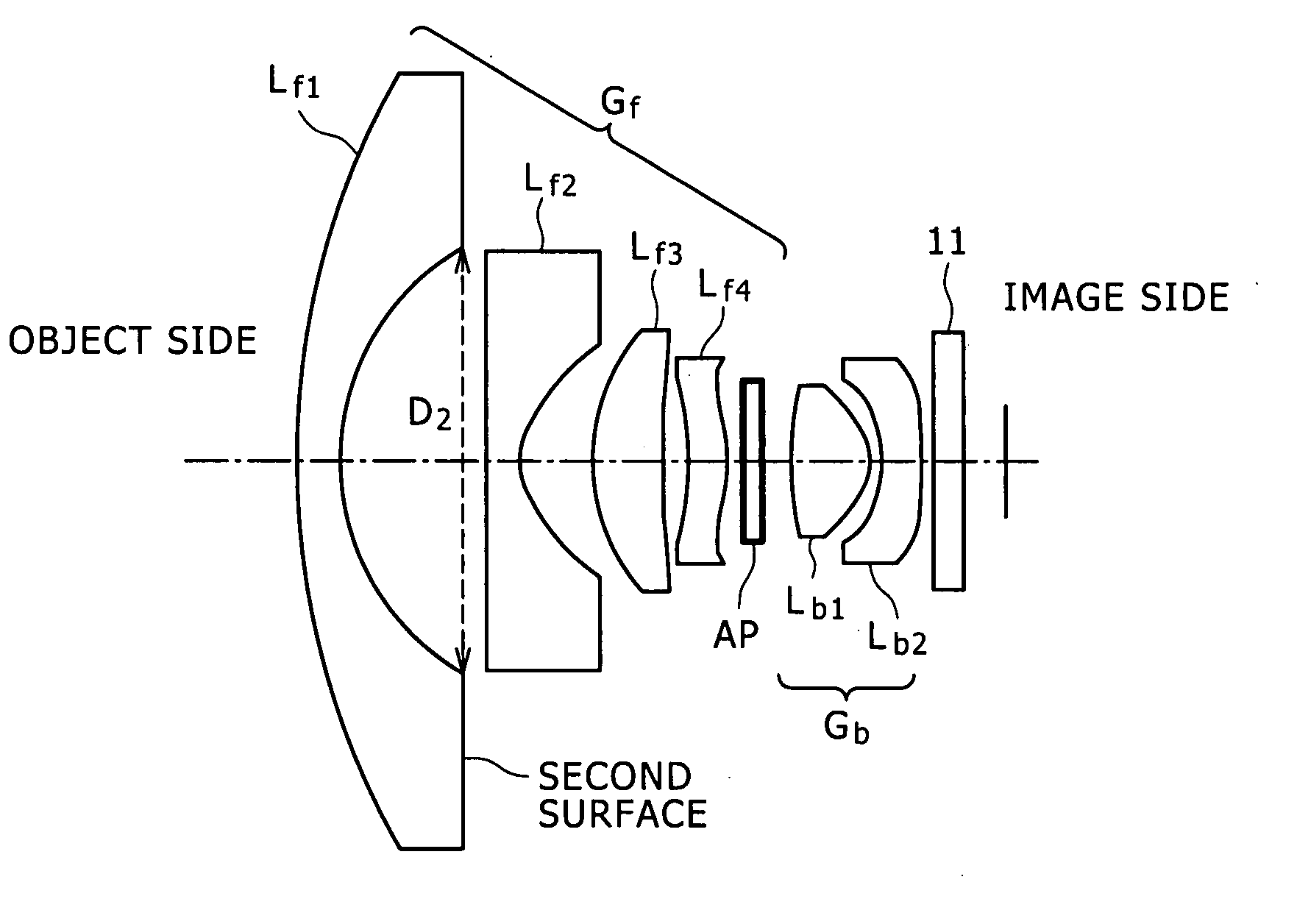
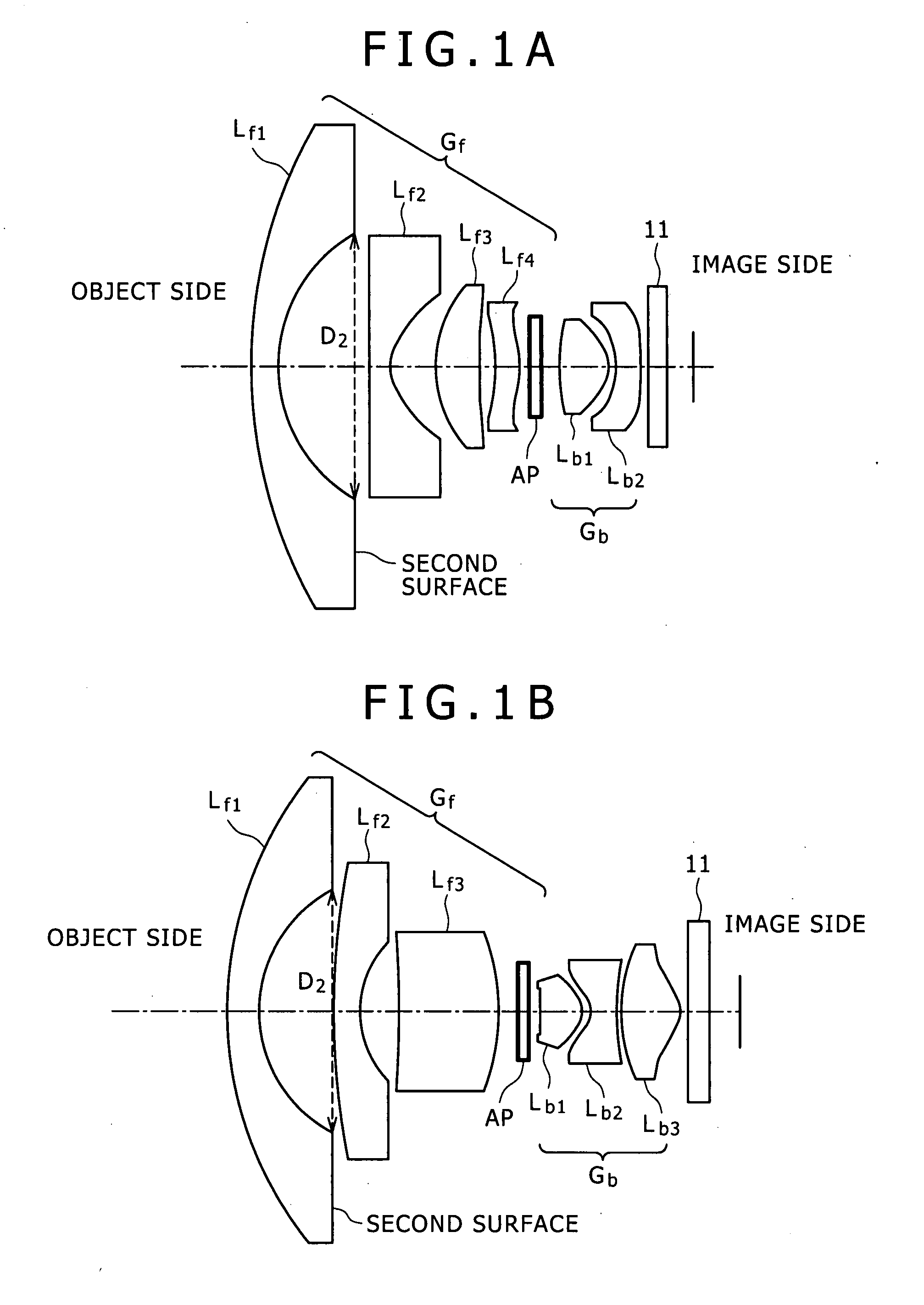
[0062] Embodiment 1 pertains to a lens unit according to one embodiment of the present invention, specifically a lens unit according to the first mode of the invention, more particularly a fisheye lens unit. A conceptual diagram of the lens unit according Embodiment 1 is shown in FIG. 1A. The lens unit in Embodiment 1 is a 2-group 6-lens lens unit, which includes a front group Gf of lenses, a stop AP, and a back group Gb of lenses, in this order from the object side toward the image side. The front group Gf includes:

[0063] (A-1) a first lens Lf1 having a negative (having negative power) meniscus shape;

[0064] (A-2) a negative (having negative power) second lens Lf2 formed from a plastic and having an aspherical surface;

[0065] (A-3) a positive (having positive power) third lens Lf3; and

[0066] (A-4) a positive (having positive power) fourth lens Lf4,

in this order from the object side toward the image side.

In addition, the back group Gb includes:

[0067] (B-1) a positive (having ...

embodiment 2

[0078] Embodiment 2 is a modification of Embodiment 1, and pertains to a lens unit, specifically a fisheye lens unit, according to the second mode of the present invention. A conceptual diagram of the lens unit in Embodiment 2 is shown in FIG. 1B. The lens unit in Embodiment 2, also, is a 2-group 6-lens lens unit including a front group Gf of lenses, a stop AP, and a back group Gb of lenses, in this order from the object side toward the image side. The front group Gf includes:

[0079] (A-1) a first lens Lf1 having a negative (having negative power) meniscus shape;

[0080] (A-2) a negative (having negative power) second lens Lf2 formed from a plastic and having an aspherical surface; and

[0081] (A-3) a positive (having positive power) third lens Lf3,

in this order from the object side toward the image side.

In addition, the back group Gb includes:

[0082] (B-1) a positive (having positive power) first lens Lb1;

[0083] (B-2) a negative (having negative power) second lens Lb2; and

[0084...


PUM


Abstract

A lens unit includes a front group, a stop, and a rear group, in order from the object side toward the image side. The front group includes at least: a first lens having a negative meniscus shape; a negative second lens formed from a plastic and having an aspherical surface; and a positive third lens, in order from the object side toward the image side. The rear group includes at least: a positive first lens; and a negative second lens, in order from the object side toward the image side.

Description

CROSS REFERENCES TO RELATED APPLICATIONS [0001] The present invention contains subject matter related to Japanese Patent Application JP 2006-075531 filed with the Japanese Patent Office on Mar. 17, 2006, the entire contents of which being incorporated herein by reference. BACKGROUND OF THE INVENTION [0002] 1. Field of the Invention [0003] The present invention relates to a lens unit. [0004] 2. Description of the Related Art [0005] As a lens unit, for example a fisheye lens unit, suitable for incorporation into an image pickup apparatus or the like having a small image pickup device, there has been known a fisheye lens unit having a total of four lenses, as for examples disclosed in Japanese Patent Laid-open No. 2005-227426 (hereinafter referred to as Patent Document 1). SUMMARY OF THE INVENTION [0006] However, in such a fisheye lens unit as disclosed in Patent Document 1, for obtaining excellent optical characteristics, the optical overall length should be enlarged to or above 15 mm...

Claims


Application Information

Patent Timeline
Patent Type & Authority Applications(United States)
IPC IPC(8): G02B9/04
CPCG02B9/60G02B13/04G02B13/0045G02B9/62
Inventor BABA, TOMOHIKO
Owner SONY CORP
Learn More