Patterned media and method of manufacturing the same, and magnetic recording apparatus

a technology of magnetic recording media and patterned media, which is applied in the field of patterned media and a method of manufacturing the same, and the manufacture of magnetic recording apparatus, can solve the problems of affecting the flight characteristics of the magnetic head, the inability to improve the track density of the magnetic recording media installed in the hard disk drive (hdd), and the inability to achieve the same

Inactive Publication Date: 2007-09-20
KK TOSHIBA
View PDF72 Cites 53 Cited by
  • Summary
  • Abstract
  • Description
  • Claims
  • Application Information

AI Technical Summary

Problems solved by technology

In recent years, a problem that improvement in track density in magnetic recording media installed in hard disk drives (HDD) is prevented because of interference between adjacent tracks has become obvious.
In particular, to reduce a fringing effect of magnetic fields from a magnetic head has become an important technical problem.
The reason of using such a method is because it has been believed that the flying characteristics of a magnetic head are made unstable when the depths of recesses on the surface thereof are too

Method used


Image

  • Patterned media and method of manufacturing the same, and magnetic recording apparatus
  • Patterned media and method of manufacturing the same, and magnetic recording apparatus
  • Patterned media and method of manufacturing the same, and magnetic recording apparatus

Examples


example 1

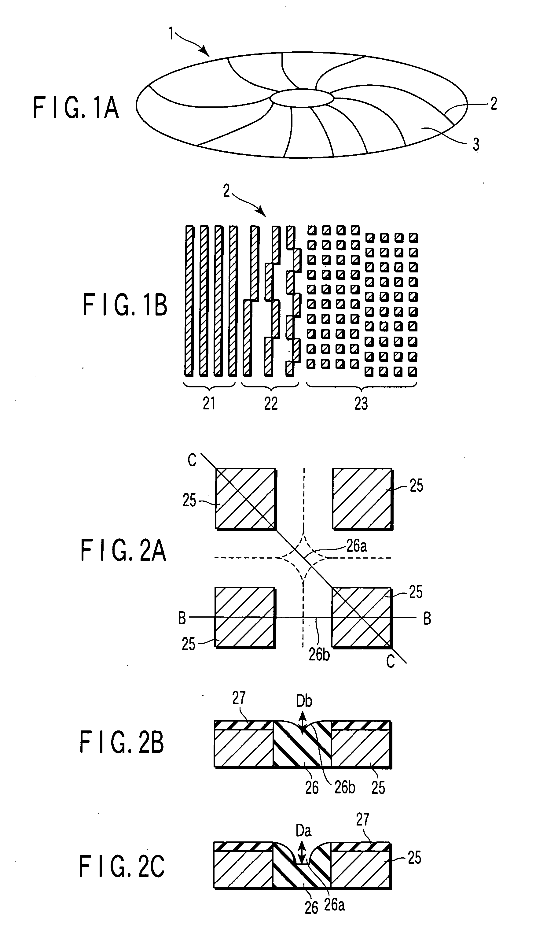
[0089]A stamper in which only the marks of preamble, address, and burst in the servo areas are formed of recessed patterns by electron beam lithography was prepared. Using the stamper, a patterned media was manufactured by the method shown in FIGS. 7A to 7H. In this patterned media, protruded magnetic patterns are formed in the servo areas, and there are no patterns in the data areas. The burst mark in the manufactured patterned media had a size of 180 nm in one side.

[0090]The depths of recesses on the surface of the patterned media were measured with an atomic force microscope (AFM). The depth Da from the surface of the burst mark to the surface of the nonmagnetic material filled in the second central part 26a at the portion surrounded by the four burst marks shown in FIG. 2C was 10 nm. The depth Db from the surface of the burst mark to the surface of the nonmagnetic material filled in the first central part 26b between the burst marks adjacent to each other in the cross-track dire...

example 2

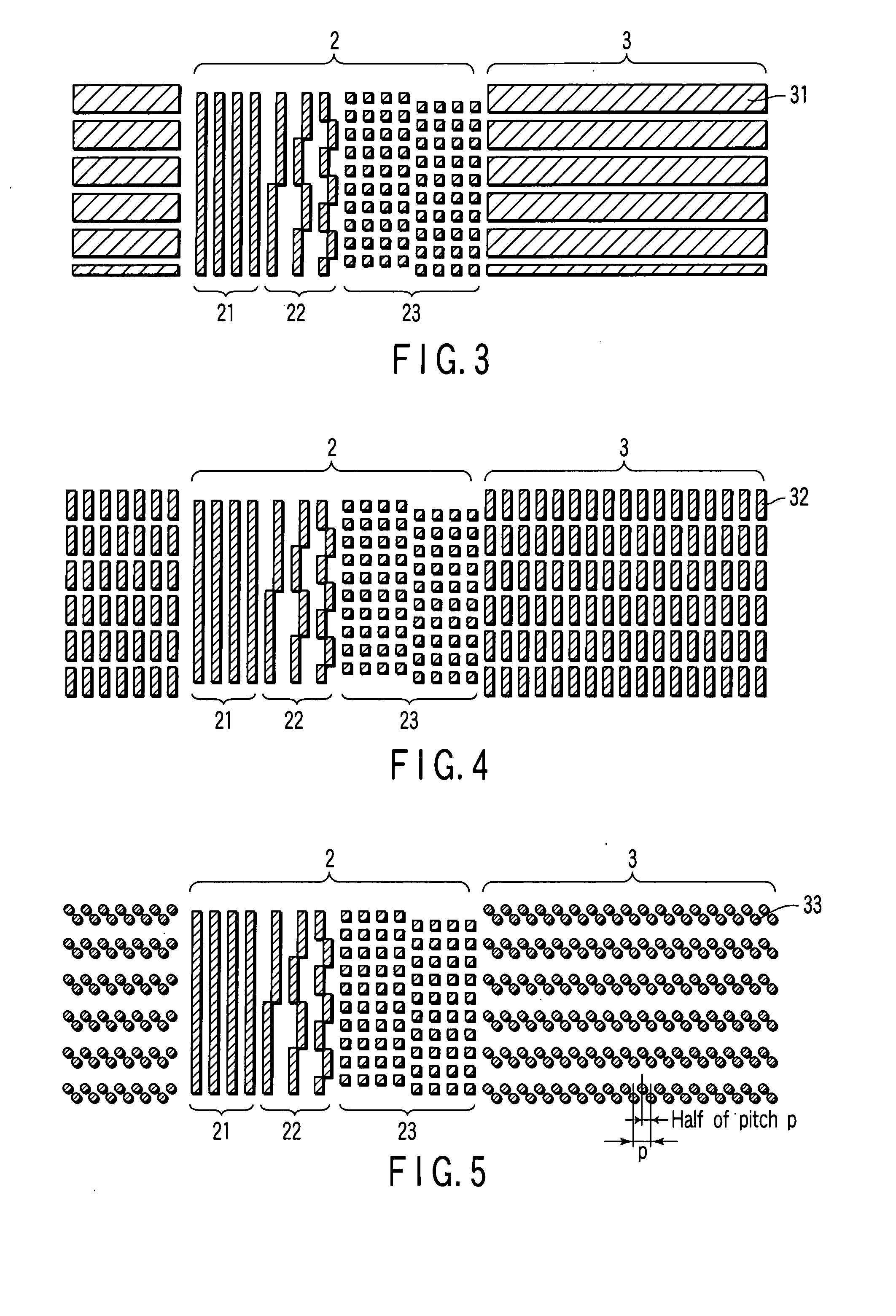
[0096]A stamper in which the marks of preamble, address, and burst in the servo areas, and recording tracks are formed of recessed patterns by electron beam lithography was prepared. Using the stamper, a patterned media was manufactured by the method shown in FIGS. 7A to 7H. The burst mark in the manufactured patterned media had a size of 180 nm in one side, and the track had a width of 150 nm.

[0097]When the depths of recesses on the surface of the patterned media were measured with the AFM, it was found that Da was 10 nm and Db was 5 nm. The cross-section of the recording track part was the same as FIG. 2B, and the depth from the surface of the recording track to the surface of the nonmagnetic material filled in the first central part between the recording tracks was 5 nm which is the same as the depth Db.

[0098]A hard disk drive (HDD) to which the patterned media had been mounted was manufactured, and head output signals were measured with the oscilloscope. As a result, the amplitu...

example 3

[0104]A stamper in which the marks of preamble, address, and burst in the servo areas, and discrete bits in the recording tracks are formed of recessed patterns by electron beam lithography was prepared. Using the stamper, a discrete bit media shown in FIG. 4 was manufactured by the method shown in FIGS. 7A to 7H. The burst mark in the manufactured patterned media had a size of 180 nm in one side, and the discrete bit had a size of 150 nm×50 nm.

[0105]In this discrete bit media, the recording track part had the same cross-sectional structure as that of the burst part. Namely, given that a depth from the surface of the discrete bit to the surface of the nonmagnetic material filled in the first central part between the discrete bits adjacent to each other in the cross-track direction or the down-track direction is Db, and a depth from the surface of the discrete bit to the surface of the nonmagnetic material filled in the second central part at the portion surrounded by the four discre...


PUM


Abstract

A patterned media has a substrate, and a magnetic recording layer on the substrate including protruded magnetic patterns and a nonmagnetic material filled in between the protruded magnetic patterns. In the patterned media, a depth Db and a depth Da, which are defined that Db is a depth from a surface of the magnetic patterns to a surface of the nonmagnetic material filled in a first central part between the magnetic patterns adjacent to each other in a cross-track direction or a down-track direction, and Da is a depth from a surface of the magnetic patterns to a surface of the nonmagnetic material filled in a second central part in a portion surrounded by the magnetic patterns, have a relationship that the depth Da is greater than the depth Db.

Description

CROSS-REFERENCE TO RELATED APPLICATIONS[0001]This application is based upon and claims the benefit of priority from prior Japanese Patent Application No. 2006-072857, filed Mar. 16, 2006, the entire contents of which are incorporated herein by reference.BACKGROUND OF THE INVENTION[0002]1. Field of the Invention[0003]The present invention relates to a patterned media and a method of manufacturing the same, and a magnetic recording apparatus provided with the patterned media.[0004]2. Description of the Related Art[0005]In recent years, a problem that improvement in track density in magnetic recording media installed in hard disk drives (HDD) is prevented because of interference between adjacent tracks has become obvious. In particular, to reduce a fringing effect of magnetic fields from a magnetic head has become an important technical problem.[0006]With respect to such a problem, a discrete track recording type patterned media (DTR media) in which recording tracks are physically sepa...

Claims


Application Information

Patent Timeline
IPC IPC(8): G11B5/82
CPCB82Y10/00G11B5/59655G11B5/855G11B5/82G11B5/743
Inventor KAMATA, YOSHIYUKISAKURAI, MASATOSHISHIROTORI, SATOSHIKIMURA, KAORI
Owner KK TOSHIBA
Why Eureka
Try Eureka