Illuminating Panel and Illuminating Device

a technology of illumination panel and illuminating device, which is applied in the direction of fixed installation, lighting and heating apparatus, lighting support devices, etc., can solve the problems of many limitations on installation, and achieve the effects of high illumination, uniform illuminance distribution, and high illumination

Inactive Publication Date: 2007-09-20
MEERE
View PDF2 Cites 41 Cited by
  • Summary
  • Abstract
  • Description
  • Claims
  • Application Information

AI Technical Summary

Benefits of technology

[0018] According to the illuminating panel of the invention, as a linear light source unit is configured of: a light emitter having light emitting diodes linearly installed thereon; a first reflector formed of parabolic surfaces; and a second reflector having flat plate-like reflecting surfaces arranged farther to the light emergence side than the first reflector, the first reflector reflects light from the light emitting diodes toward the light emergence side while making it approximately parallel, and the second reflector reflects light from the light emitting diodes, which has not fallen incident on the first reflector, toward the light emergence side while making it approximately parallel, thereby enabling a power saving and yet an illuminance distribution equalization with a high illuminance. Furthermore, as the linear light source units are annularly disposed on the module panel, an irradiated area having a high illuminance and a uniform illuminance distribution, obtained by the individual linear light source units, can be expanded uniformly in all directions from a center of the irradiated area. In addition, an overlapping irradiated area having a higher illuminance and a uniform illuminance distribution, which is irradiated with light from all the linear light source units, can be formed in a central portion of the expanded irradiated area. As a result, it is possible to, while saving power, form the overlapping irradiated area, which has a high illuminance and a stable flat illuminance distribution, with a long irradiation distance.
[0019] According to the illuminating device, as a plurality of the illuminating panels is connected and arranged in an array formation, by arraying minimum unit module panels each provided with the linear light source unit, an overlapping irradiated area having a high illuminance and a uniform illuminance distribution can be developed into an optional width with ease.

Problems solved by technology

A hitherto known luminaire has used various types of illuminating light sources, such as a fluorescent lamp, an incandescent lamp and a spot light, but there have been many limitations on its installation due to its illuminating light containing an ultraviolet component inducing a deterioration of an illuminated subject and to a heat generation of the illuminating light sources.

Method used


Image

  • Illuminating Panel and Illuminating Device
  • Illuminating Panel and Illuminating Device
  • Illuminating Panel and Illuminating Device

Examples


Embodiment Construction

[0043] Hereafter, a detailed description will be given, with reference to the drawings, of a preferred embodiment of an illuminating panel and an illuminating device according to the invention.

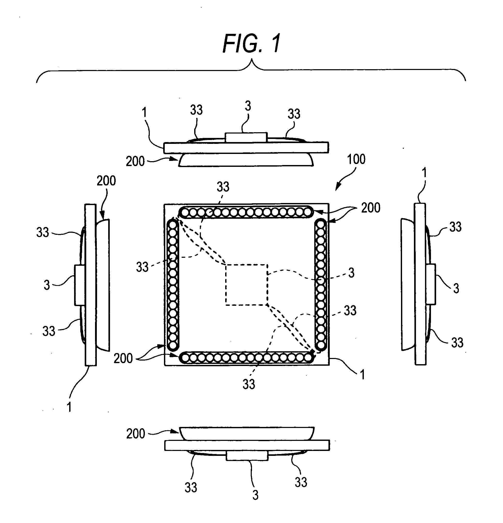
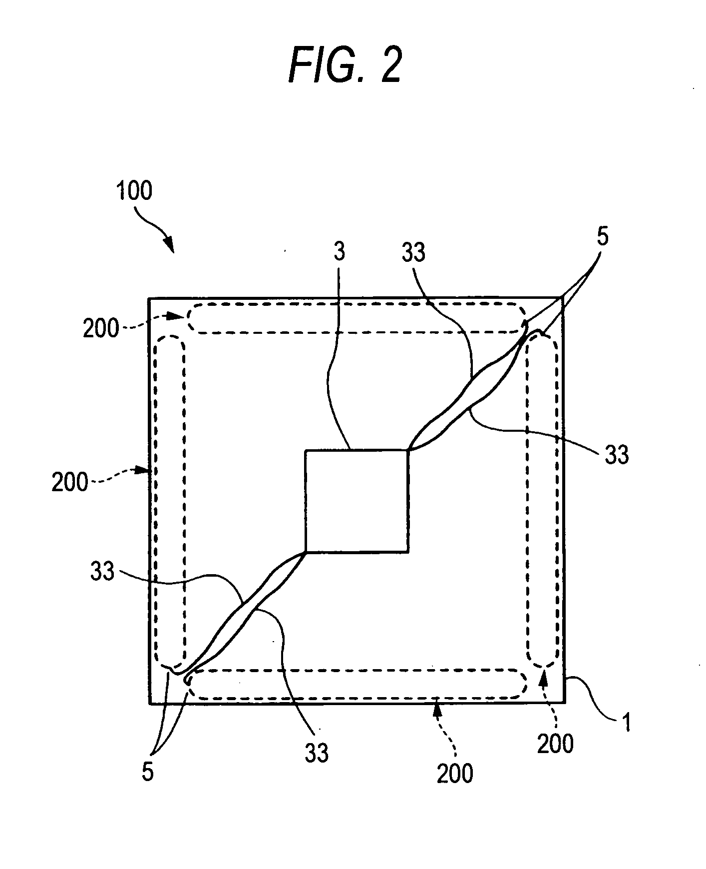
[0044]FIG. 1 is an external view, including a bottom view of the illuminating panel according to the invention in the center, and side views thereof seen from four directions on the left, right, top and bottom, and FIG. 2 is a plan view (a view showing the backside of FIG. 1) of the illuminating panel shown in FIG. 1 as seen from above.

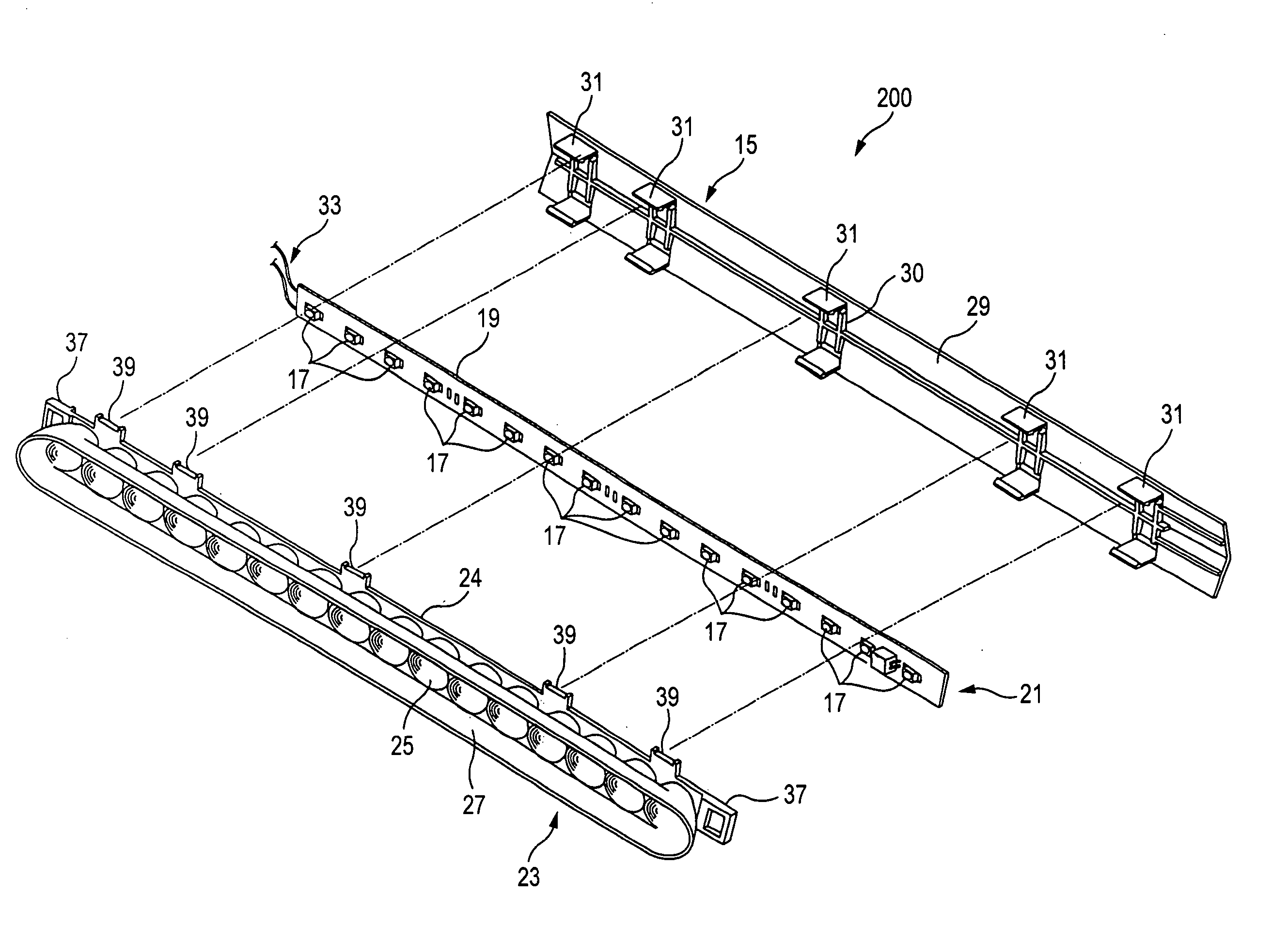
[0045] An illuminating panel 100 has a plurality (in the embodiment, four) of linear light source units 200, to be described hereafter, disposed annularly (in the embodiment, in a quadrangular formation) on a module panel 1 made of an opaque resin material or the like. When the module panel 1 is installed, a surface thereof, on which is disposed the linear light source unit 200, is used as a lower surface, and an upper surface opposite thereto is attached to a...


PUM


Abstract

The invention has an object of obtaining an illuminating panel by which an illuminated area having a high illuminance and a stable flat illuminance distribution can be formed with a long irradiation distance while power is being saved. An illuminating panel 100 has disposed thereon a plurality of linear light source units 200, and the linear light source units 200 each include: a light emitter having a plurality of light emitting diodes linearly installed on a base; a first reflector formed of parabolic surfaces which are provided on a light emergence side of the light emitter in such a way as to correspond to the plurality of light emitting diodes, and light emitting faces of which fall in focal positions; and a second reflector having a pair of flat plate-like reflecting surfaces which, being arranged with the light emitting diodes sandwiched therebetween, farther to the light emergence side than the first reflector and parallel to an array direction of the light emitting diodes, reflect light from the light emitting diodes toward the light emergence side, wherein the linear light source units 200 are annularly disposed on a module panel.

Description

TECHNICAL FIELD [0001] The present invention relates to an illuminating panel and an illuminating device. BACKGROUND ART [0002] A hitherto known luminaire has used various types of illuminating light sources, such as a fluorescent lamp, an incandescent lamp and a spot light, but there have been many limitations on its installation due to its illuminating light containing an ultraviolet component inducing a deterioration of an illuminated subject and to a heat generation of the illuminating light sources. Recently, since an LED light source having less heat generation and power consumption has attracted more attention, and a white LED having a high luminance has also been provided, there is an increasing number of luminaires for general lighting using the LED light source. An example of this kind of illuminating device is disclosed in, for example, Patent Document 1. [0003] Also, to date, in a case of an illuminating device, in order to obtain a desired illuminance, individual lumina...

Claims


Application Information

Patent Timeline
Patent Type & Authority Applications(United States)
IPC IPC(8): F21V1/00F21S2/00F21S8/04F21Y101/02
CPCF21K9/00F21V7/005F21V7/06F21V7/09Y10S362/80F21V19/0035F21Y2101/02F21Y2105/00F21Y2103/003F21V17/164F21Y2103/10F21Y2115/10F21K9/68F21V7/0083
Inventor HIRATSUKA, TOSHIO
Owner MEERE
Why Eureka
Try Eureka