Video coding apparatus

Active Publication Date: 2007-09-20
FUJITSU LTD
3 Cites 29 Cited by

AI-Extracted Technical Summary

Problems solved by technology

An information volume of a video is generally very large, making it highly costly if media accumulation or network transmission is carried out utilizing the original form of the video.
Meanwhile, the process volume of detection of a motion vector greatly increases with the size of the search range or the number of search positions, and therefore a tradeoff exists between image quality and the circuit size and/or a power consumption of an apparatus.
This is because the resolution of color difference is finer as compared to that of a brightness component, limiting the degradation of a subjective image quality to a minimum if only the resolution of the color difference part is reduced.
Such a motion vector detection method using only a brightness component does not have difficulties in handling a common image, whereas it allows for degraded prediction accuracy of a motion vector in the case of an image in which a brightness component is uniform (i.e., nonexistence of a texture) and also a texture exists only in a...

Method used

[0045]In addition to the above described configuration, a embodiment of the present invention is configured to reduce the information volume of a brightness component by rounding down a post-quantization coefficient of the brightness component in order to prevent the information volume from becoming excessively large as a result of making a quantization parameter smaller in the small block in which the prediction accuracy of a motion vector has degraded. This is because there usually is some amount of prediction error included in, namely, “only a brightness component is uniform” and therefore in...

Benefits of technology

[0034]Either of the configurations described above reduces the information volume of a brightness component in image information after a quantization.
[0035]As explained above, the present invention is co...

Abstract

A video coding apparatus carries out a compression coding of a video based on a result of predicting a motion vector predicted between frames of the video. A quantization parameter control unit comprised of the apparatus calculates a ratio of an accumulation value, in the small block, of a prediction error of a brightness component to an accumulation value, in the small block, of a prediction error of a color difference component at the time that a motion vector detection/compensation unit which carries out a motion compensation based on a prediction result of the motion vector for the small block designated in a frame of the above video as a prediction accuracy indicator of the foregoing motion vector, and carries out a control of a quantization unit executing a quantization of image information of the small block based on the prediction accuracy indicator.

Application Domain

Technology Topic

Image

  • Video coding apparatus
  • Video coding apparatus
  • Video coding apparatus

Examples

  • Experimental program(1)

Example

[0041]The first description is of an outline of an embodiment according to the present invention.
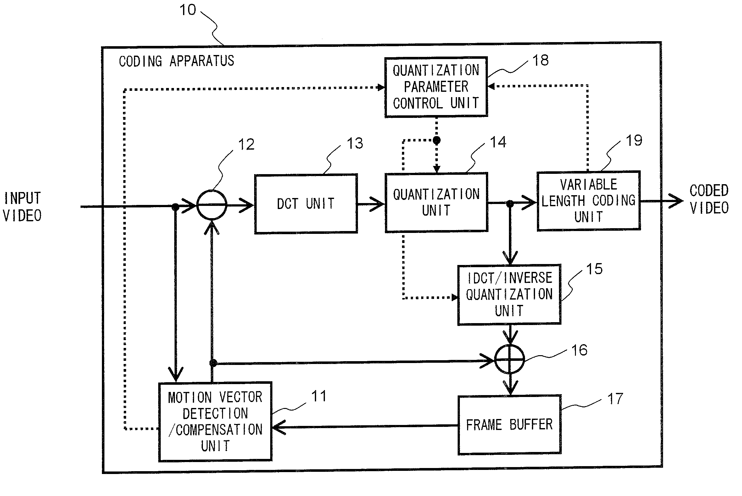
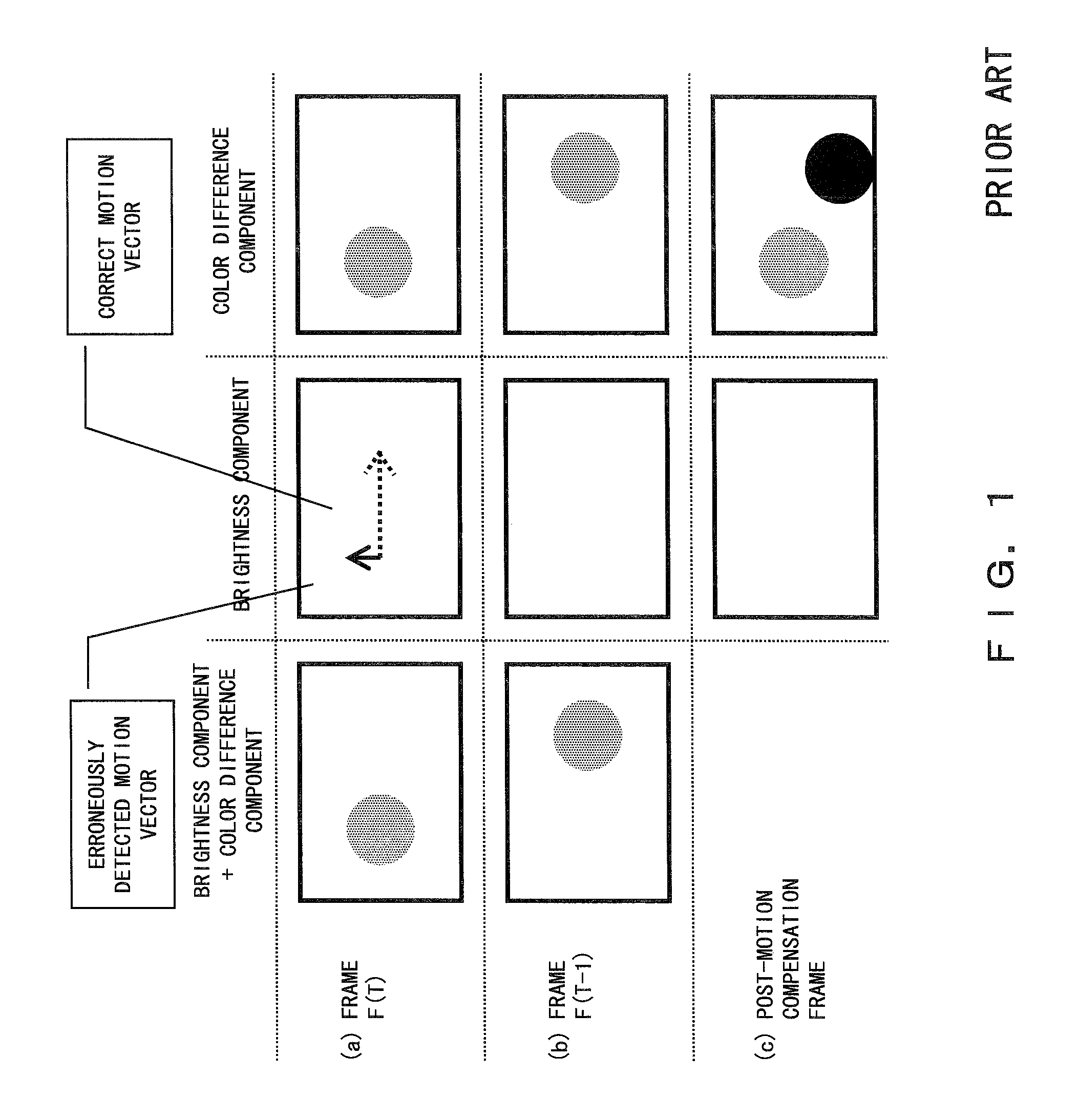
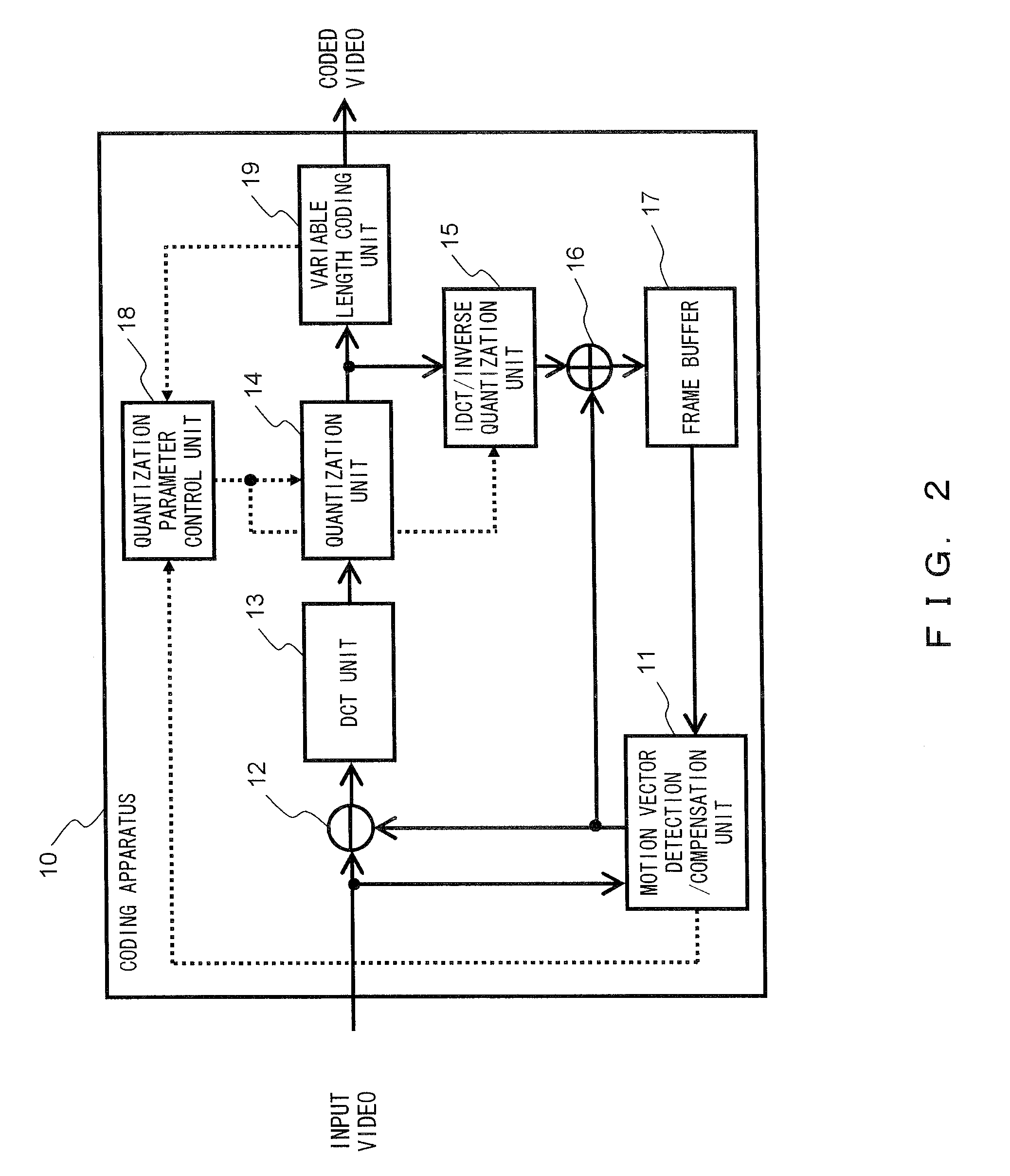
[0042]In the case where a brightness component is uniform with a texture existing only in a color difference component in a certain small block within a screen, the prediction accuracy of a motion vector degrades. Since the brightness component is uniform in this event, a degradation of prediction accuracy of the motion vector creates a small prediction error accumulation value of the brightness component. Meanwhile, the prediction error accumulation value of the color difference component is relatively large as compared to that of the brightness component.
[0043]Accordingly, an embodiment of the present invention is configured to calculate a ratio of a prediction error accumulation value of a brightness component to a prediction error accumulation value of a color difference component as an indicator of prediction accuracy of a motion vector. When the indicator indicates a degradation of the prediction accuracy of a motion vector, the present embodiment is configured to judge it as a small block whose subjective image quality possibly degrades and makes a quantization parameter smaller than other small blocks.
[0044]This configuration reduces the influence of making the quantization parameter small if a ratio of the number of small blocks of which the prediction accuracy of a motion vector has degraded to the number of small blocks within a screen is small, thereby improving subjective image quality of the small block of which the prediction accuracy of a motion vector has degraded while maintaining a subjective image quality of other small blocks.
[0045]In addition to the above described configuration, a embodiment of the present invention is configured to reduce the information volume of a brightness component by rounding down a post-quantization coefficient of the brightness component in order to prevent the information volume from becoming excessively large as a result of making a quantization parameter smaller in the small block in which the prediction accuracy of a motion vector has degraded. This is because there usually is some amount of prediction error included in, namely, “only a brightness component is uniform” and therefore increased information volume as a result of making the quantization parameter small cannot be ignored in the case of a bit rate being limited. Besides, such a round down causes a minimal degradation of the subjective image quality because the main component of an image is a color difference component rather than a brightness component in such a case.
[0046]Note that the provision here is a first method for reducing all values to zero (“0”) if the absolute values of post-quantization coefficient are less than a threshold value, and a second method for widening a dead zone for a quantization as a method for rounding down a post-quantization coefficient.
[0047]The following is a description of an embodiment of the present invention by referring to the accompanying drawings:
[0048]First is a description relating to FIG. 2, which illustrates a configuration of a coding apparatus 10 embodying the present invention.
[0049]A motion vector detection/compensation unit11 performs, by using only a brightness component, a prediction of a motion vector between a processing frame of an input video and a reference frame which is stored by a frame buffer 17 and which has been locally decoded in the past, and determines the most optimal motion vector per each of the small blocks of the image. In addition, the unit 11 generates a motion compensation frame based on the aforementioned reference frame and the most optimal motion vector, and outputs it to a subtracter 12. It further notifies a quantization parameter control unit 18 of the accumulated value of the error (simply “error accumulation value” hereinafter) between the processing frame of the input video and generated motion compensation frame separately for a brightness component and for a color difference component.
[0050]The error accumulation value SAD_Y of brightness components and error accumulation value SAD_C of color difference components relating to the processing frame of the input video and generated motion compensation frame are calculated as follows:
SAD_Y = ∑ i = 0 N - 1 org_Y [ i ] - pred_Y [ i ] SAD_C = ∑ i = 0 M - 1 org_Cb [ i ] - pred_Cb [ i ] + ∑ i = 0 M - 1 org_Cr [ i ] - pred_Cr [ i ]
[0051]In the above noted expressions, the org_Y[ ], org_Cb[ ] and org_Cr[ ] are the brightness (Y) component, color difference (Cb) component and color difference (Cr) component, respectively, which are included in a small block of the processing frame of the input video. The pred_Y [ ], pred_Cb [ ] and pred_Cr [ ] are the brightness (Y) component, color difference (Cb) component and color difference (Cr) component, respectively, of a predicted small block based on a detected motion vector. Meanwhile, the N and M are the numbers of respective samples of the brightness (Y) components and color difference (Cb and Cr) components which are included in the small block.
[0052]The subtracter12 performs a subtraction process between a processing frame of the input video and a motion compensation frame output from the motion vector detection/compensation unit 11.
[0053]A DCT unit 13 carries out a frequency conversion by applying a discrete cosine transform (DCT) operation to a prediction error pixel output from the subtracter 12.
[0054]A quantization unit 14 carries out a quantization process for the frequency-converted prediction error pixel according to a quantization parameter and an instruction for a reduction of a brightness component information volume that are handed from the quantization parameter control unit 18.
[0055]An IDCT/inverse quantization unit 15 applies an inverse quantization process and an inverse discrete cosine transform (IDCT) operation to the output of the quantization unit 14 by using the quantization parameter handed from the quantization parameter control unit 18.
[0056]An adder 16 generates a local decode frame by adding the output of the IDCT/inverse quantization unit 15 and that of the motion vector detection/compensation unit 11.
[0057]The frame buffer 17 is memory temporarily retaining the local decode frame output from the adder 16.
[0058]The quantization parameter control unit 18 determines a quantization parameter and also issues an instruction to the quantization unit 14 for reducing a brightness component information volume if required by the aforementioned determination value.
[0059]A variable length coding unit 19 applies a variable length coding to the frequency-converted, quantized motion prediction error pixel value.
[0060]The next description is relative to FIG. 3, which shows a flow chart of a detail of a control process carried out by the quantization parameter control unit 18.
[0061]Referring to FIG. 3, first, the S101 carries out a process for obtaining generation information volume at the variable length coding unit 19, and the subsequent S102 carries out a process of calculating a quantization parameter, constituting a basis, by each small block of an image based on the obtained generated information volume. The quantization parameter QP can be calculated by a various known method as a rate management method strictly observing a bit rate limitation. For instance, the method disclosed in the above listed Laid-Open Japanese Patent Application Publication No. 07-107481, No. 2001-522174 or No. 2002-64829 can be utilized.
[0062]Likewise, the processes in S103 and thereafter are carried out for each small block of the image.
[0063]Then S103 carries out a process for obtaining an error accumulation value SAD_Y of brightness components and an error accumulation value SAD_C of color difference components which are notified from the motion vector detection/compensation unit 11, and the subsequent S104 carries out a process for calculating the above described motion vector prediction accuracy indicator, that is, a ratio of the obtained error accumulation value of brightness components SAD_Y to error accumulation value of color difference components SAD_C. Then the subsequent S105 carries out a process for judging whether or not the aforementioned indicator indicates a degradation of the prediction accuracy of the motion vector.
[0064]Note that a judgment of whether or not a quantization parameter QP is to be smaller may be made according to whether or not the following expression is valid:
(SAD—Y*TH)SAD—C;
where the TH is an externally provided parameter. That is, in the case of the above noted expression being valid, the ratio of an error accumulation value of color difference components SAD_C to an error accumulation value of brightness components SAD_Y (i.e., (SAD_C)/(SAD_Y)) is larger than a predefined threshold value. Accordingly, this is precisely the case where prediction accuracy of a motion vector shall be determined as degraded according to the present invention. Incidentally, the above described 4:2:0 formed color image is for instance provided with “3” as a value of the TH.
[0065]If the prediction accuracy of the motion vector is judged to be degraded in the judgment process in the S105 (i.e., the judgment result being “yes”), the S106 applies a reduction process represented by the following expression to the quantization parameter QP calculated based on the generation information volume at the variable length coding unit 19:
QP′=QP−Offset
[0066]Note that a value of the Offset in the above noted expression uses “6” (e.g., in the case of the AVC/H.264). Then the subsequent S107 carries out a process for notifying the quantization unit 14 and IDCT/inverse quantization unit 15 of the quantization parameter QP′ obtained by the above expression.
[0067]Contrarily, if the prediction accuracy of the motion vector is determined “not degraded” in the judgment process of S105 (i.e., the judgment result being “no”), the process proceeds to S107—without performing the process of S106—for carrying out the process for notifying the quantization unit 14 and IDCT/inverse quantization unit 15 of the quantization parameter QP which has been calculated in the process of S102.
[0068]Then, the S108 carries out the process for judging whether or not the generation information volume obtained by the process of S101 is within a predefined value (e.g., a bit rate predefined for the coding apparatus 10). If it is judged to be within the predefined value (i.e., the judgment result being “yes”), the process returns to the S101 followed by repeating the above described processes. Contrarily, if it is judged not to be within the predefined value (i.e., the judgment result being “no”), the process proceeds to the S109.
[0069]The S109 carries out the process for judging whether the above described first method or second method is what is preset for the coding apparatus 10 as a method for reducing a generation information volume of a brightness component after a quantization. In this event, if the first method is preset, the S110 carries out the process for notifying the quantization unit 14 of an instruction for reducing an information volume of the brightness component by changing all post-quantization coefficients whose absolute values are smaller than a threshold (e.g., “1”) to zero (“0). Comparably, if the second method is preset, the S111 carries out the process for notifying the quantization unit 14 of an instruction for reducing an information volume of the brightness component by widening a dead zone width for a quantization.
[0070]Next is a further description of the second method for reducing the information volume of a brightness component by widening a dead zone width for a quantization. A process of quantization by the quantization unit 14 can be expressed by the following expression for example:
c′=(c+(dz QP−1)))>>(QP)
[0071]In the above expression, the “<<” represents a left bit shift, while the “>>” represents a right bit shift. The c is a pre-quantization coefficient, and c′ is a post-quantization coefficient. The QP is a quantization parameter and the above expression represents a quantization of the coefficient c by a 2QP value. Incidentally, “dz” is a parameter for determining a dead zone width for a quantization. Here, making a value of dz smaller widens a dead zone width, and the post-quantization coefficient becomes smaller.
[0072]In the above noted expression, assume the case in which c=6 (which is “110” in a binary number), QP=3 and dz=0.5. In this case, (dz<<(QP−1))=2 (which is “10” in a binary number), and therefore (c+(dz<<(QP−1)))=8 (which is “1000” in a binary number). Therefore, c′=1 (which is also “1” in a binary number).
[0073]Meanwhile, also assume the case in which dz=0.25 by widening the dead zone width in the above described case. Since (dz<<(QP−1))=1 (which is also “1” as a binary number) in this case and therefore, (c+(dz<<(QP−1)))=7 (which is “111” in a binary number). Accordingly, c′=0. This is a manner for suppressing the post-quantization information volume of a brightness component as a result of making a quantization parameter small.
[0074]When the process of the above described S110 or S111 finishes, S110 or S111, the process returns to S101 for repeating the above-described processes.
[0075]The quantization parameter control unit 18, in carrying out the above described processes determines a quantization parameter and instructs the quantization unit 14 for a reduction of a brightness component information volume, if required by the aforementioned determination value.
[0076]The coding apparatus 10, configured as illustrated by FIG. 2, operates as described above, and therefore reduces degradation of subjective image quality in a part in which prediction accuracy of a motion vector, due to only the brightness component being uniform (even if only a brightness component), is used for detecting a motion vector because of limitation, et cetera, of a circuit size or power consumption.
[0077]Note that encoding of a video carried out by the coding apparatus 10 shown by FIG. 2 can be carried out by a computer with a standard configuration, that is, by a computer 30 which comprises a CPU (central processing unit) 31 for administering operation control of the entirety of the computer 30, RAM 32 (random access memory) used for work by the CPU 31 as required at the time of carrying out various processes, ROM 33 (read only memory) pre-storing a basic control program executed by the CPU 31 and various kinds of data used at the time of executing the program on an as required basis, a magnetic disk storage apparatus 34 storing various control programs executed by the CPU 31 and various kinds of data used at the time of executing the program on an as required basis, a data reading apparatus 35 for reading various kinds of data recorded in a portable recording medium 40 such as CD (compact disk), MO (magneto optical) disk and DVD (digital versatile disk) for example, an input unit 36, comprising a pointing device, such as mouse apparatus, and a keyboard apparatus, et cetera, for obtaining an user instruction corresponding to the content of an operation thereon, a display unit 37 for displaying a prescribed image according to a CPU instruction and an I/F (interface) unit 38 for exchanging various kinds of data with other equipments as shown by FIG. 4.
[0078]In order to embody the present invention by such a configured computer 30, it is only necessary to generate a control program and store it in the above described portable recording medium 40 for making the CPU 31 of the computer 30 carry out the control process shown in FIG. 3. These processes are carried out by the quantization parameter control unit 18 according to the above described embodiment, followed by making the computer 30 read the control program and having the CPU 31 execute the program.
[0079]Incidentally, an alternative configuration may exist in which a storage medium for storing the above described control program uses a storage apparatus 61 comprised by a computer system functioning as a program server 60. This computer system (program server 60) is connected to a telecommunications line 50 (e.g., the Internet) in place of the portable recording medium 40. A configuration in this case may be such as to transmit a transmission signal, which is obtained by modulating a carrier wave by a data signal expressing the above described control program, to the computer 30 from the program server 60 by way of the telecommunications line 50 that is a transmission medium. At the computer 30, a reception of the transmission signal and a reproduction of the original control program through a demodulation enable the CPU 31 to execute the control program.
[0080]While the embodiment of the present invention is described above, the present invention is in no way limited thereby.

PUM

no PUM

Description & Claims & Application Information

We can also present the details of the Description, Claims and Application information to help users get a comprehensive understanding of the technical details of the patent, such as background art, summary of invention, brief description of drawings, description of embodiments, and other original content. On the other hand, users can also determine the specific scope of protection of the technology through the list of claims; as well as understand the changes in the life cycle of the technology with the presentation of the patent timeline. Login to view more.

Similar technology patents

Classification and recommendation of technical efficacy words

  • Reduce volume
  • Reduce image quality

Implant release mechanism

ActiveUS20080140178A1Reduce volumeReduce outer diameterStentsOcculdersDilatorStent
Owner:COOK MEDICAL TECH LLC

Flash storage chip and flash array storage system

ActiveUS20080052451A1Reduce volumeImprove data transmission rateMemory adressing/allocation/relocationData transmissionPCI Express
Owner:PHISON ELECTRONICS

Devices and methods for placement of partitions within a hollow body organ

InactiveUS20070167960A1Reduce volumeSuture equipmentsStapling toolsTissue acquisitionBody organs
Owner:ETHICON ENDO SURGERY INC

Radiographic image conversion panel

Owner:KONICA MINOLTA INC
Why Eureka
Try Eureka