Lens barrel, photographic device, and production method of same

a technology of lens barrel and production method, which is applied in the field of lens barrel and photographic device, can solve the problem that the prior lens barrel cannot reduce and achieve the effect of reducing the effect of catoptric ligh

Active Publication Date: 2007-09-20
NIKON CORP
View PDF8 Cites 10 Cited by
  • Summary
  • Abstract
  • Description
  • Claims
  • Application Information

AI Technical Summary

Benefits of technology

[0005] An object of the present invention is to provide a lens barrel and a camera system enabling to reduce effects of catoptric light.
[0022] at least said barrel-side mount projection is formed on said barrel-side fitting unit to avoid cross-section of light path area where object light is introduced in said camera body.
[0025] said bayonet unit is arranged to avoid light flux entering in said photographic region among light flux going to the side of said photographic region.
[0075] The present invention can provide a lens barrel enabling to reduce effects of catoptric light and a camera system including said lens barrel. In the present invention, an object to reduce effects of catoptric light is achieved by changing the arranged position or the size of bayonet mount projections.

Problems solved by technology

However, a prior lens barrel cannot reduce effects of catoptric light due to bayonet mounts.

Method used


Image

  • Lens barrel, photographic device, and production method of same
  • Lens barrel, photographic device, and production method of same
  • Lens barrel, photographic device, and production method of same

Examples


first embodiment

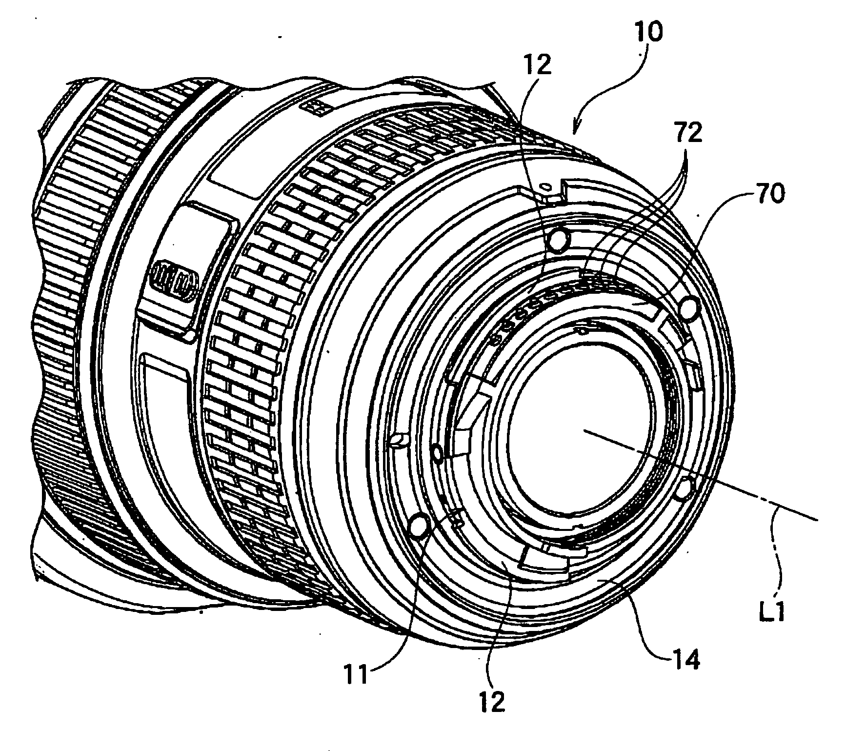
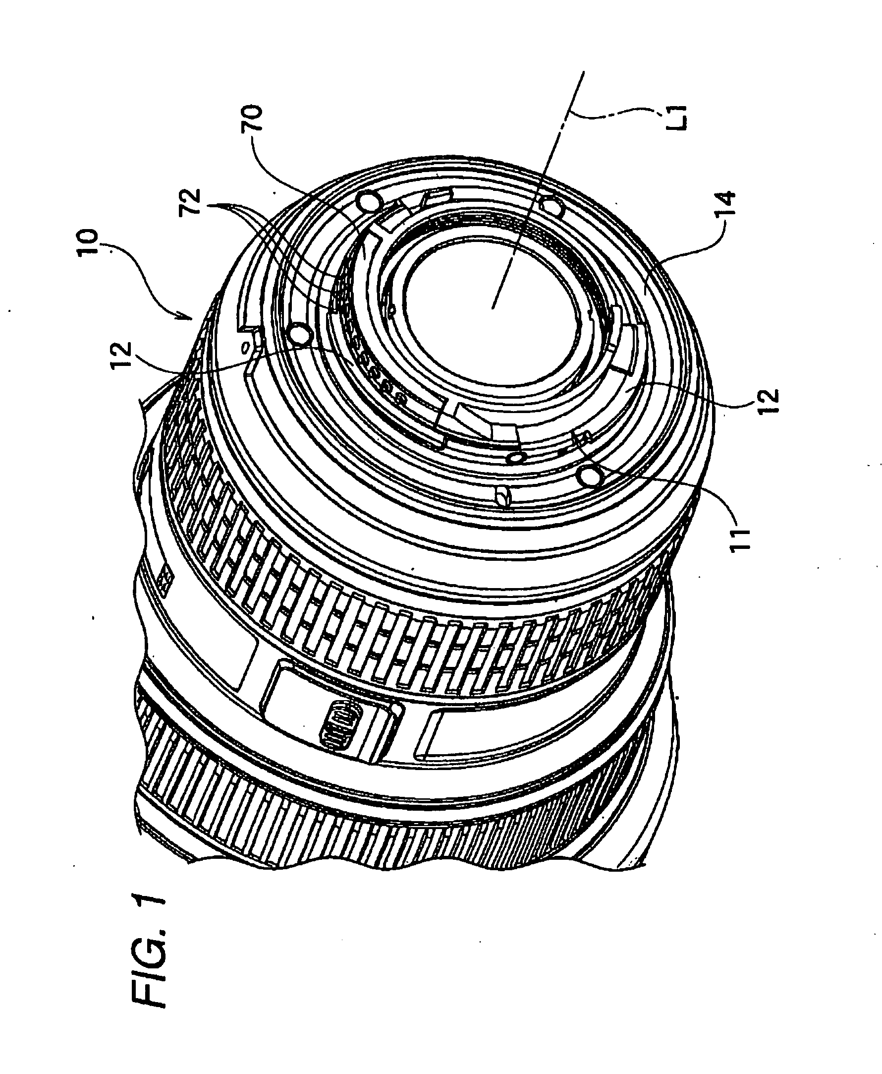
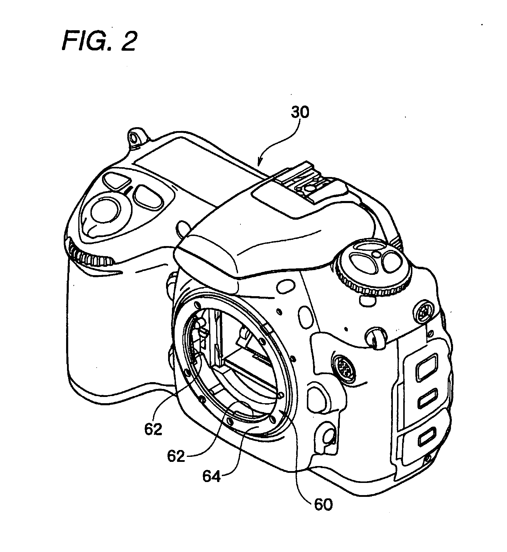
[0086] As shown in FIG. 1 and FIG. 2, a lens barrel-type imaging equipment represented by single-lens reflex camera typically includes a lens barrel 10 and a camera body 30. A lens barrel-side fitting part 11 held on the back of the lens barrel 10 is detachably attached to a body-side fitting part 60 held on the front of the camera body 30.

[0087] To the inside of a barrel body of a lens barrel 10 shown in FIG. 1, multiple optical lens groups (not shown in the figure) are attached movably in the direction of an optical axis. As shown in FIG. 3, a camera body 30 holds a low-pass filter 31 and an imaging device 32. The imaging device 32 includes magnifying-type solid-state image sensing devices such as CMOS other than CCD.

[0088] A reason to provide a low-pass filter 31 is following. In the imaging device 32 of the camera body 30, a phenomenon called a false color or a color moire can occur resulting in a different coloring from an actual one when a light with high spatial frequency e...

second embodiment

[0112] As shown in FIG. 7, in a lens barrel 10-2 according to the second embodiment in the invention, the bayonet-type mount projection 12 has the same arranged position as the mount projection 22 according to the comparative example shown in FIG. 6. However, a notch 13 is formed on the mount projection 12a so as to avoid the inner opening site 40a of the mirror box 40 in the lens barrel 10-2 in the present embodiment.

[0113] The second embodiment has advantages that it is easy to design and unnecessary to change in basic configuration of a bayonet-type mount projection 62 of the camera body 30 since the mount projections 12 can be arranged at equal intervals in the circumferential direction. Other configuration and effects in the present embodiment is same as in the above-described first embodiment.

third embodiment

[0114] As shown in FIG. 8, in a lens barrel 10-3 according to the third embodiment, each of two mount projections 12b are arranged on outside of the long sides in a cross-section of the inner opening site 40a of the mirror box 40. This configuration results in no exposure of the mount projection 12b on the inside of the opening site 40a. Other configuration and effects in the present embodiment is same as in the above-described first embodiment.


PUM


Abstract

A lens barrel comprising bayonet type mount projections to detachably attach to a lens-fitting unit of a camera body having a photographic region, wherein mount projections are formed to avoid cross-section of light path area where object light is introduced in the camera body.

Description

BACKGROUND OF THE INVENTION [0001] 1. Field of the Invention [0002] The present invention relates to a lens barrel, a photographic device and production methods of the lens barrel and the photographic device. [0003] 2. Description of the Related Art [0004] In the Japanese Unexamined Patent Publication (A) No. 2000-121904, a lens barrel is proposed to enable to change a diaphragm to cut off harmful rays in accordance with the size of the image circle. However, a prior lens barrel cannot reduce effects of catoptric light due to bayonet mounts. SUMMARY OF THE INVENTION [0005] An object of the present invention is to provide a lens barrel and a camera system enabling to reduce effects of catoptric light. [0006] A lens barrel according to a first aspect of the present invention comprises [0007] a barrel holding an optical system, and [0008] a barrel-side mount fitting said barrel on a photographic device having an imaging unit, wherein [0009] said imaging unit takes an image formed on a ...

Claims


Application Information

Patent Timeline
IPC IPC(8): G03B17/00
CPCG03B17/14H04N5/2254G03B19/12H04N23/55
Inventor FUJIWARA, MAKOTOKATAGISHI, YUUICHI
Owner NIKON CORP
Why Eureka
Try Eureka