Time/frequency recovery of a communication signal in a multi-beam configuration using a kinematic-based kalman filter and providing a pseudo-ranging feature

Inactive Publication Date: 2007-09-20
HARRIS CORP
View PDF2 Cites 53 Cited by
  • Summary
  • Abstract
  • Description
  • Claims
  • Application Information

AI Technical Summary

Benefits of technology

[0017] In accordance with the invention, the above-discussed inability of a conventional, PLL-based receiver terminal to successfully acquire and track timing and frequency offsets, associated with relative acceleration between a remote transmit site, such as a satellite, and a receive terminal, which may reside in an essentially static, shore-based environment, or in a kinematic environment, such as a surface ship or submarine, is effectively obviated by means of a new and improved, Kalman filter-based time/frequency tracke

Problems solved by technology

The level of knowledge is sufficient for a coarse time and frequency lock to the received si

Method used


Image

  • Time/frequency recovery of a communication signal in a multi-beam configuration using a kinematic-based kalman filter and providing a pseudo-ranging feature
  • Time/frequency recovery of a communication signal in a multi-beam configuration using a kinematic-based kalman filter and providing a pseudo-ranging feature
  • Time/frequency recovery of a communication signal in a multi-beam configuration using a kinematic-based kalman filter and providing a pseudo-ranging feature

Examples


Embodiment Construction

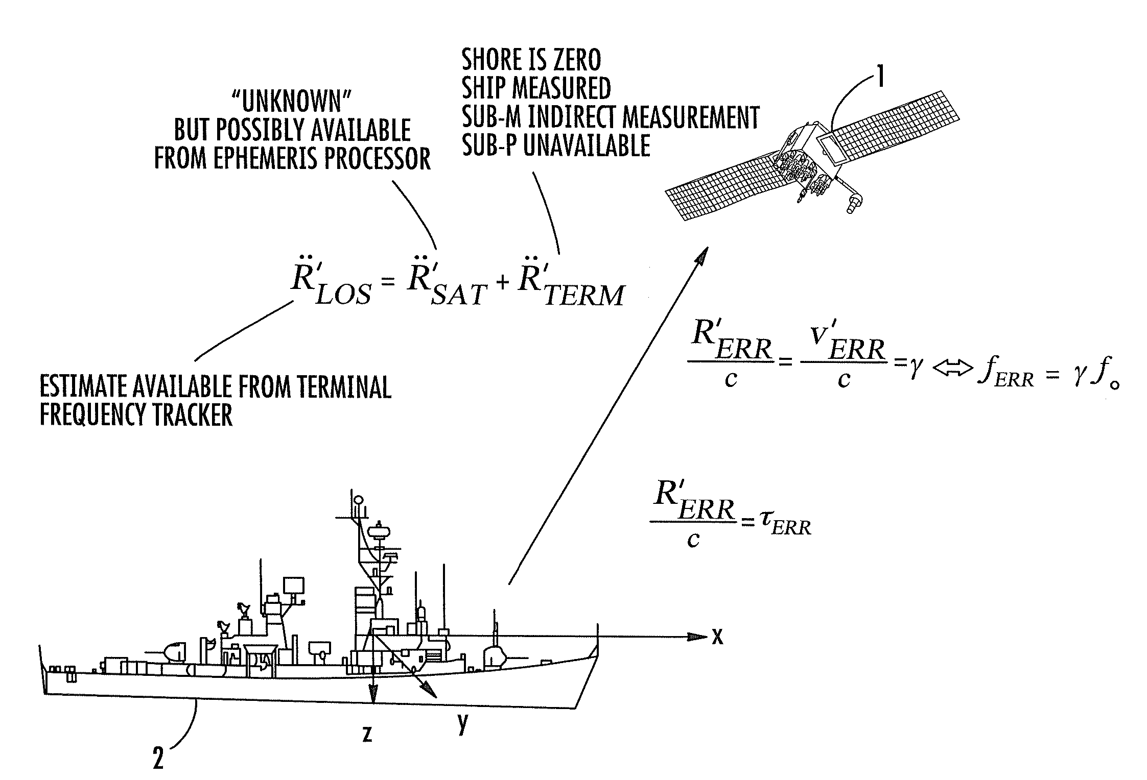
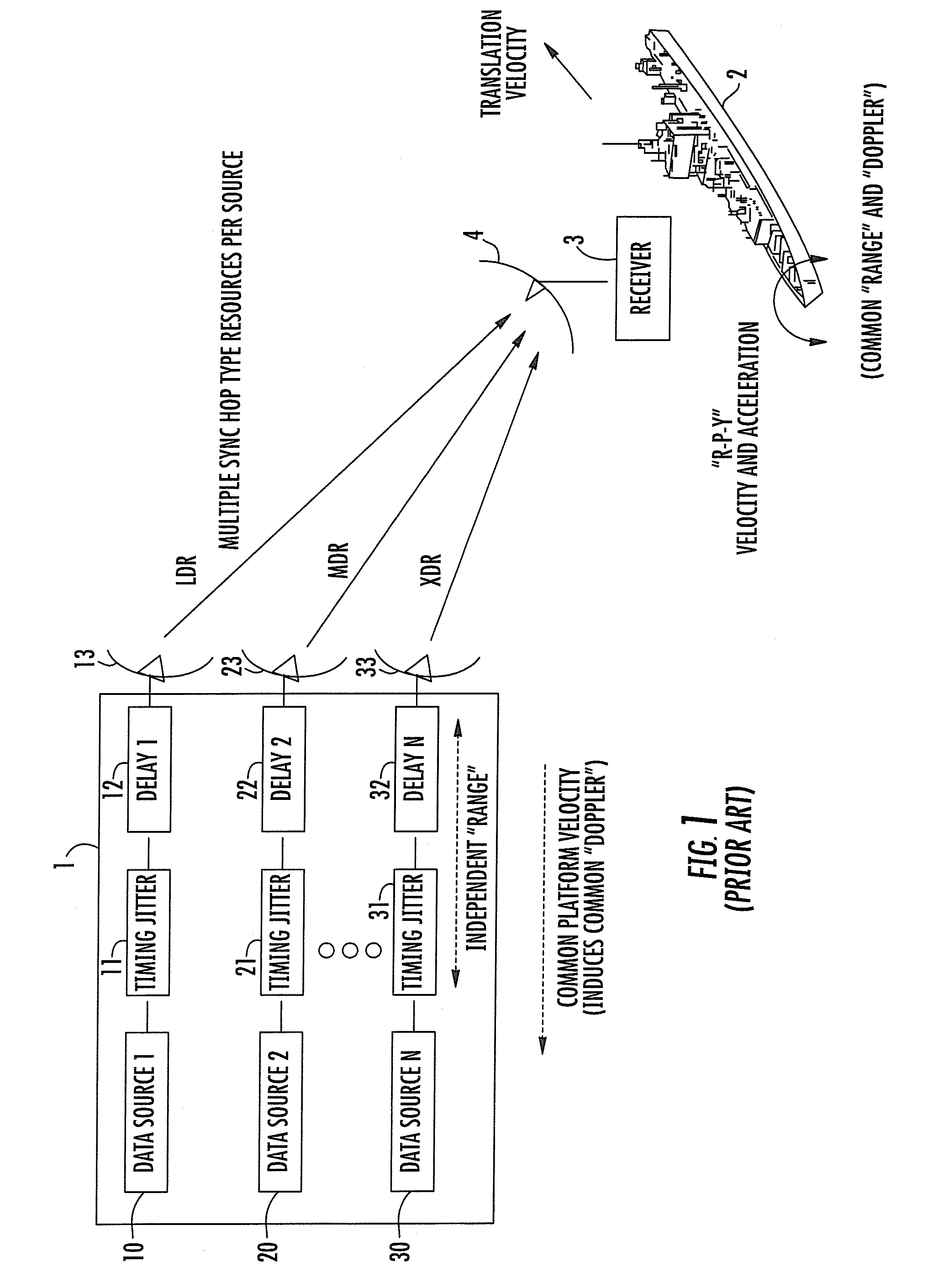
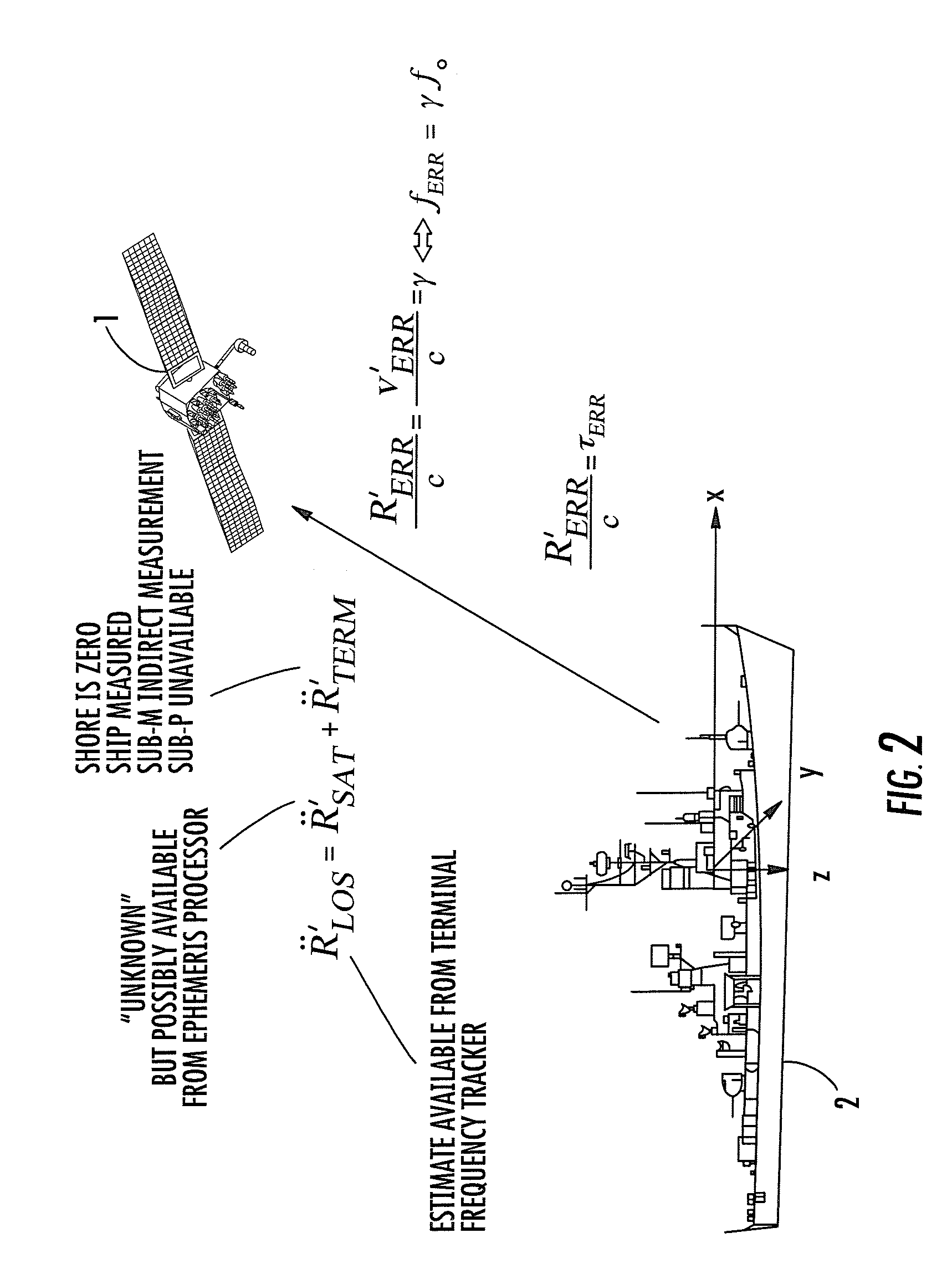
[0100] Before describing various embodiments of the kinematic domain data-updated Kalman filter-based time / frequency tracker (TFT) for a receiver terminal in accordance with the present invention, it should be observed that the invention resides primarily in a prescribed novel arrangement of conventional communication circuits and components, and attendant communication control software that resides in an attendant digital signal processor subsystem. As a result, the configuration of such circuits and components and the manner in they are interfaced with the communications control software have, for the most part, been depicted in the drawings by readily understandable functional block diagrams, which show only those specific aspects that are pertinent to the present invention, so as not to obscure the disclosure with details which will be readily apparent to those skilled in the art having the benefit of the description herein. Thus, the overall block diagram of the invention and a...


PUM


Abstract

A downlink time/frequency tracker for a receiver terminal, which may be mounted to a static platform on the earth, or to a dynamic platform, such as a ship. The tracker is operative to acquire and track time and frequency variations in time- and frequency-hopped synchronization signals from different data rate sources in a dynamic platform, such as a satellite. Characteristics of the Kalman filter are updated in accordance with data representative of timing error and frequency error measurements carried out on the synchronization signals, as well as data representative of local kinematic domain measurements carried out with respect to the receiver terminal. The Kalman filter outputs minimum mean square error estimates of timing and frequency errors in the receiver terminal's demodulator clock. These error estimates are used to synchronize the demodulator's clock with the clock embedded in the downlink signal, so as to enable demodulation and recovery of data.

Description

GOVERNMENT LICENSE RIGHTS [0001] The U.S. Government has a paid-up license in this invention and the right in limited circumstances to require the patent owner to license others on reasonable terms as provided for by the terms of contract No. AEHF-NMT N00039-04-C-0011.FIELD OF THE INVENTION [0002] The present invention relates in general to communication systems and subsystems thereof, where either the transmitter terminal and / or receiver terminal may be a mobile platform, with possibly high dynamic motion and possibly non-zero and / or non-constant acceleration between the transmitter terminal and the receiver terminal. It is particularly directed to a communication system where in each of the transmitter and receiver terminals has a single master oscillator reference that is used to provide all the transmitter and receiver terminal clocks, oscillators, and epochs respectively. The invention provides time recovery and frequency recovery of a time and frequency hopped transmitted data...

Claims


Application Information

Patent Timeline
IPC IPC(8): H04B7/00H04B15/00
CPCH04B7/18589H04B7/2675H04W56/0075H04W56/0035H04B7/2681
Inventor BEADLE, EDWARD R.DISHMAN, JOHN F.
Owner HARRIS CORP
Why Eureka
Try Eureka