Cooling mechanism for belt-based speed-change system of engine

a technology of cooling mechanism and belt, which is applied in the direction of guards, couplings, cycle equipment, etc., can solve the problems of reducing the cooling effect, and achieve the effects of enhancing performance, enhancing cooling performance, and effectively and efficiently guided

Inactive Publication Date: 2007-09-20
KYMCO
View PDF3 Cites 34 Cited by
  • Summary
  • Abstract
  • Description
  • Claims
  • Application Information

AI Technical Summary

Benefits of technology

[0011] The primary purpose of the present invention is to provide a cooling mechanism for a belt-based speed-change system of a motorcycle engine, which has enhanced cooling performance for cooling a transmission box of the belt-based speed-change system of the motorcycle engine.
[0012] To achieve the above objective, according to the present invention, a cooling mechanism for a belt-based speed-change system of a motorcycle engine comprises an air guide chamber formed inside a transmission box of the engine and defining an air collection chamber communicating with an air inlet of the transmission box. A wet-type clutch arranged between the engine and the belt-based speed-change system has a clutch cover mounted to and covering the air guide chamber and defining openings in communication with the air collection chamber. An air guide lid is arranged between the belt-based speed-change system and the clutch cover, and forms an air intake opening corresponding in position to a drive disk of the belt-based speed-change system. The cooling mechanism allows external air entering the transmission box to be effectively and efficiently guided through the transmission box and expelled through an air outlet of the transmission box for cooling the belt-based speed-change system with enhanced performance.

Problems solved by technology

This affects the flow of air and thus decreases the cooling effect.

Method used


Image

  • Cooling mechanism for belt-based speed-change system of engine
  • Cooling mechanism for belt-based speed-change system of engine
  • Cooling mechanism for belt-based speed-change system of engine

Examples


Embodiment Construction

[0020] The following descriptions are of exemplary embodiments only, and are not intended to limit the scope, applicability or configuration of the invention in any way. Rather, the following description provides a convenient illustration for implementing exemplary embodiments of the invention. Various changes to the described embodiments may be made in the function and arrangement of the elements described without departing from the scope of the invention as set forth in the appended claims.

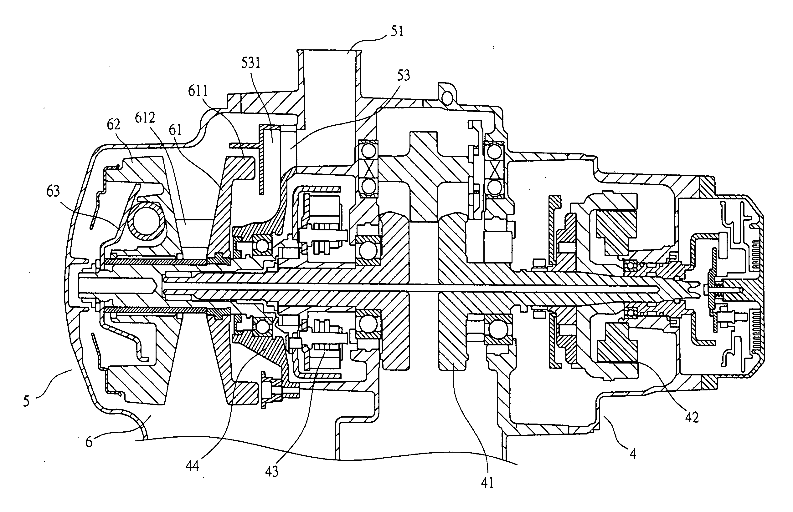
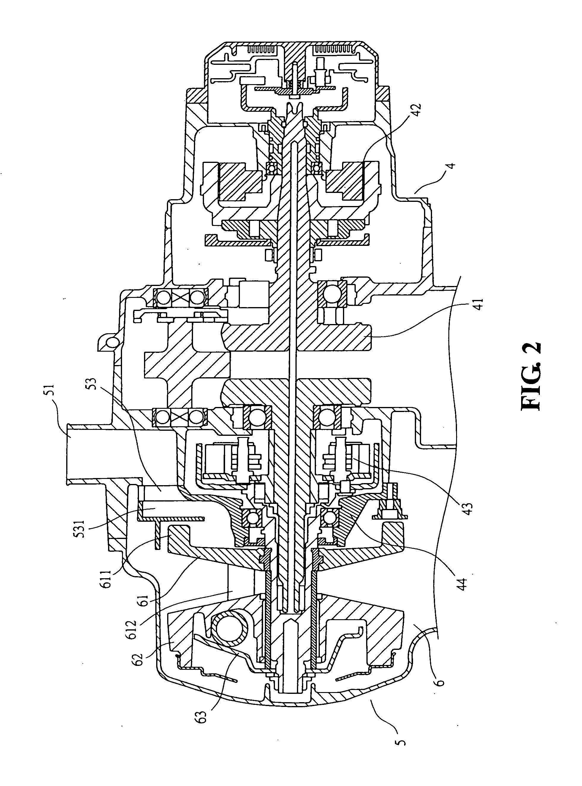
[0021] With reference to the drawings and in particular to FIG. 2, a motorcycle engine, which is designated with reference numeral 4, comprises a crankshaft 41 for output of power. The crankshaft 41 has an end coupled to a generator 42 and an opposite end extending into a transmission box 5 and coupled to a drive disk 61, a slide disk 62, and a constraint board 63 of a belt-based speed-change system 6. A wet-type clutch 43 is arranged at one side of the drive disk 61 of the belt-based speed-cha...


PUM


Abstract

Disclosed is a cooling mechanism for cooling a belt-based speed-change system of an engine. The engine has a crankshaft for output of power, and the crankshaft has an end coupled to a power generator and an opposite end extending into a transmission box and coupled to the belt-based speed-change system. A wet-type clutch is arranged between the belt-based speed-change system and the engine. The wet-type clutch has a clutch cover separating the clutch from the belt-based speed-change system. The transmission box forms an air inlet and an air outlet on front and rear sides thereof, respectively. An air guide chamber is formed inside the transmission box and defines an air collection chamber communicating with the air inlet. The clutch cover is mounted to and covers the air guide chamber and defines openings in communication with the air collection chamber. An air guide lid is arranged between the belt-based speed-change system and the clutch cover, and forms an air intake opening corresponding in position to a drive disk of the belt-based speed-change system. The cooling mechanism allows external air entering the transmission box to be effectively and efficiently guided through the transmission box and expelled through the air outlet for cooling the belt-based speed-change system with enhanced performance.

Description

BACKGROUND OF THE INVENTION [0001] (a) Technical Field of the Invention [0002] The present invention relates to a cooling mechanism for belt-based speed-change system of engine, and in particular to a low temperature air flow guide structure for enhancing cooling performance for the belt-based speed-change system. [0003] (b) Description of the Prior Art [0004] A motorcycle comprises an engine, which is shown in FIG. 1 of the attached drawings, and is designated with reference numeral 1. The motorcycle also comprises a transmission box 2 that is arranged next to the engine 1 and that comprises a belt-based speed-change mechanism 3. The operation of the engine starts with drawing a mixture of fuel and air into the engine 1, followed by ignition to cause combustion of the fuel-air mixture. The combustion of fuel-air mixtures significantly increases the volume of gas inside the engine cylinder and induces a force driving the piston to move along the cylinder. The piston has a rod connec...

Claims


Application Information

Patent Timeline
Patent Type & Authority Applications(United States)
IPC IPC(8): B62J13/00F16H57/02
CPCF16H57/035F16H57/0415F16H2057/02065F16H2057/0203F16H57/0489
Inventor HO, CHAO-CHANG
Owner KYMCO
Why Eureka
Try Eureka