Low-cost contour cuff for surgical tourniquet systems

a tourniquet and low-cost technology, applied in the field of pneumatic tourniquet cuffs, can solve the problems of proximal and distal snug fit, substantially higher and more hazardous inflation, and tendency to roll or slide distally on the limb

Active Publication Date: 2007-09-20
MCEWEN JAMES A +3
View PDF45 Cites 35 Cited by
  • Summary
  • Abstract
  • Description
  • Claims
  • Application Information

AI Technical Summary

Problems solved by technology

However, when applied to a patient with a tapered limb, a cylindrical cuff will not optimally match the limb taper, and will typically result in a snug fit proximally and a loose fit distally.
Consequently, a cylindrical cuff may prove unable to achieve a bloodless field distal to the cuff at normal pressures or may require a substantially higher and more hazardous inflation pressure to achieve a bloodless field, and when inflated may have a tendency to roll or slide distally on the limb during a surgical procedure.
The thick laminate construction and rigid stiffener included by Robinette-Lehman makes skewing the respective overlapping ends of the cuff difficult, and when skewed the orientation of the fixed fastening system may not be appropriate to safely and effectively allow the complete engagement of the velcro-type fastener to secure the cuff on the limb when inflated.
Although the cuff described by McEwen '431 provides increased safety and improved shape-matching over a wide range of limb tapers, it does so by including a number of expensive components and laminated materials, with subassemblies that are labor-intensive and time-consuming to manufacture.
As a result, the contour cuff of McEwen '431 has a high cost of manufacture, preventing its cost-effective use as sterile disposable tourniquet cuff for single surgical procedures.
Manufacturing the ring assemblies described in McEwen '431 requires relatively large amounts of different materials, and requires numerous labor-intensive steps including cutting, alignment, sewing and welding, all of which must be completed by skilled operators.

Method used


Image

  • Low-cost contour cuff for surgical tourniquet systems
  • Low-cost contour cuff for surgical tourniquet systems
  • Low-cost contour cuff for surgical tourniquet systems

Examples


Embodiment Construction

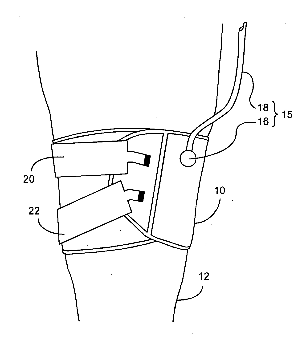
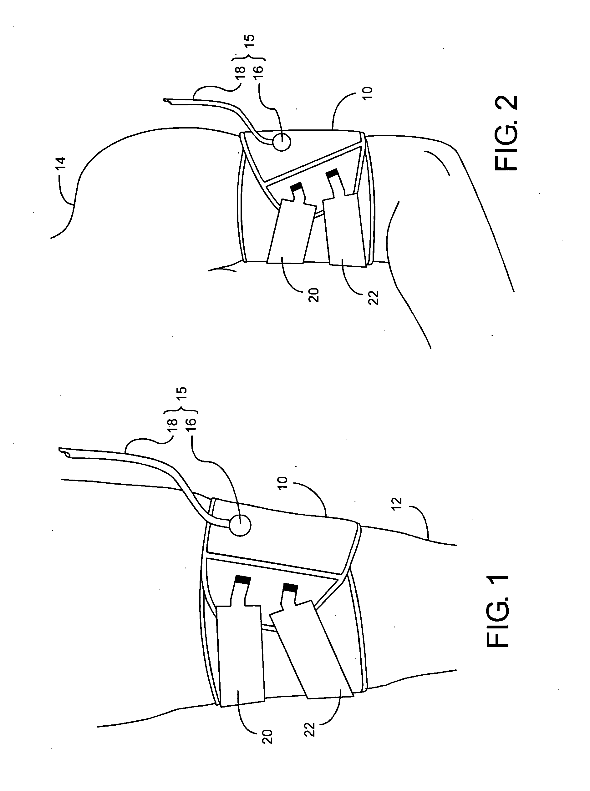
[0013]FIG. 1 shows the preferred embodiment in a surgical application and depicts contour tourniquet cuff 10 secured circumferentially around a tapered patient limb 12. FIG. 2 depicts contour cuff 10 secured circumferentially around a substantially cylindrically shaped patient limb 14.

[0014] Referring to FIG. 1, the inflatable portion of contour tourniquet cuff 10 completely encircles patient limb 12 and is inflated by a source of pressurized gas to a pressure that will occlude the flow of arterial blood in patient limb 12 distal to cuff 10. Cuff port 15 is comprised of port inlet 16 and tubing 18 and provides a gas tight pneumatic passageway to the inflatable portion of cuff 10. Tubing 18 is made from flexible thermoplastic tubing and is permanently bonded to port inlet 16. Tubing 18 is fitted with a suitable connector (not shown) to permit attachment to a tourniquet instrument such as that described by McEwen et al. in U.S. patent application Ser. No. 11 / 122,600, for the inflatio...


PUM


Abstract

A low-cost contour cuff for surgical tourniquet systems comprises: a sheath containing an inflatable bladder, the sheath having an arcuate shape, an outer surface and a centerline equidistant between first and second side edges; a securing strap non-releasably attached to the outer surface and formed of substantially inextensible material having a shape that is predetermined and substantially flat, wherein the strap includes a bending portion near a first strap end and a fastening portion near a second strap end, and wherein the bending portion is adapted to allow twisting of the bending portion out of the substantially flat shape to facilitate positioning of the fastening portion into any of a plurality of positions in the substantially flat shape; and fastening means for releasably attaching the fastening portion of the securing strap to the outer surface whenever the sheath is curved into a position for surrounding a limb.

Description

FIELD OF THE INVENTION [0001] This invention pertains to pneumatic tourniquet cuffs commonly used for stopping arterial blood flow into a portion of a surgical patient's limb to facilitate the performance of a surgical procedure, and for facilitating intravenous regional anesthesia. BACKGROUND OF THE INVENTION [0002] Typical surgical tourniquet systems of the prior art include a tourniquet cuff which encircles the limb of a surgical patient and a tourniquet instrument which is releasably connected to an inflatable bladder within the tourniquet cuff through a length of tubing, thereby establishing a gas-tight passageway between the cuff and the tourniquet instrument. The tourniquet instrument contains a pressurized gas source which is used to inflate and regulate the pressure in the tourniquet cuff above a minimum pressure required to stop arterial blood flow distal to the cuff, for a duration suitably long for the performance of a surgical procedure. Many types of surgical tournique...

Claims


Application Information

Patent Timeline
Patent Type & Authority Applications(United States)
IPC IPC(8): A61B17/00
CPCA61B17/135
Inventor MCEWEN, JAMESJAMESON, MICHAELGLINZ, KENNETHUPWARD, ALLEN
Owner MCEWEN JAMES A
Why Eureka
Try Eureka