Expandable support device and method of use

a support device and expandable technology, applied in the direction of osteosynthesis devices, internal osteosynthesis, prosthesis, etc., can solve the problems of cement mixture leaking from the bone, pain and spinal deformity with comorbidities, degradation or injury of the bone structure of the spine,

Active Publication Date: 2007-09-20
STOUT MEDICAL GROUP
View PDF103 Cites 356 Cited by
  • Summary
  • Abstract
  • Description
  • Claims
  • Application Information

AI Technical Summary

Benefits of technology

[0026] In addition, it is contemplated that the ratio of the expansion for the expandable devices (the ratio of the unexpanded height or diameter, depending on configuration, to the expanded height or diameter) may be from 1:2 to 1:5 or greater. For intravertebral and intervertebral applications applicants have found that expansion ratios of from about 1:3 to about 1:4 are acceptable. For vertebroplasty or interbody applications it is contemplated that a device having an initial height or diameter from about 4 mm (0.16 in.) to about 8 mm (0.31 in.) and an expanded height or diameter from about 7 mm (0.28 in.) to about 18 mm (0.71 in.) may be desirable.

Problems solved by technology

Some conditions of the spine result from degradation or injury to the bone structures of the spine, typically the vertebral body.
These can be the result of bone degeneration such as through osteoporosis or trauma, such as compression fractures. breakdown or injury to the boney structures in the spine can result in pain and spinal deformity with comorbidities.
The cement mixture can leak from the bone, potentially entering a dangerous location such as the spinal canal.
The cement mixture, which is naturally viscous, is difficult to inject through small diameter needles, and thus many practitioners choose to “thin out” the cement mixture to improve cement injection, which ultimately exacerbates the leakage problems.
This further exacerbates the leakage.
The mixture also fills or substantially fills the cavity of the compression fracture and is limited to certain chemical composition, thereby limiting the amount of otherwise beneficial compounds that can be added to the fracture zone to improve healing.
Other ailments of the spine result in degeneration of the spinal disc in the intervertebral space between the vertebral bodies.
In either case, disc degeneration can cause pain and other complications.
This can relieve pain in the short term, but also often increases the risk of long-term problems and can result in motor and sensory deficiencies resulting from the surgery.

Method used


Image

  • Expandable support device and method of use
  • Expandable support device and method of use
  • Expandable support device and method of use

Examples


Embodiment Construction

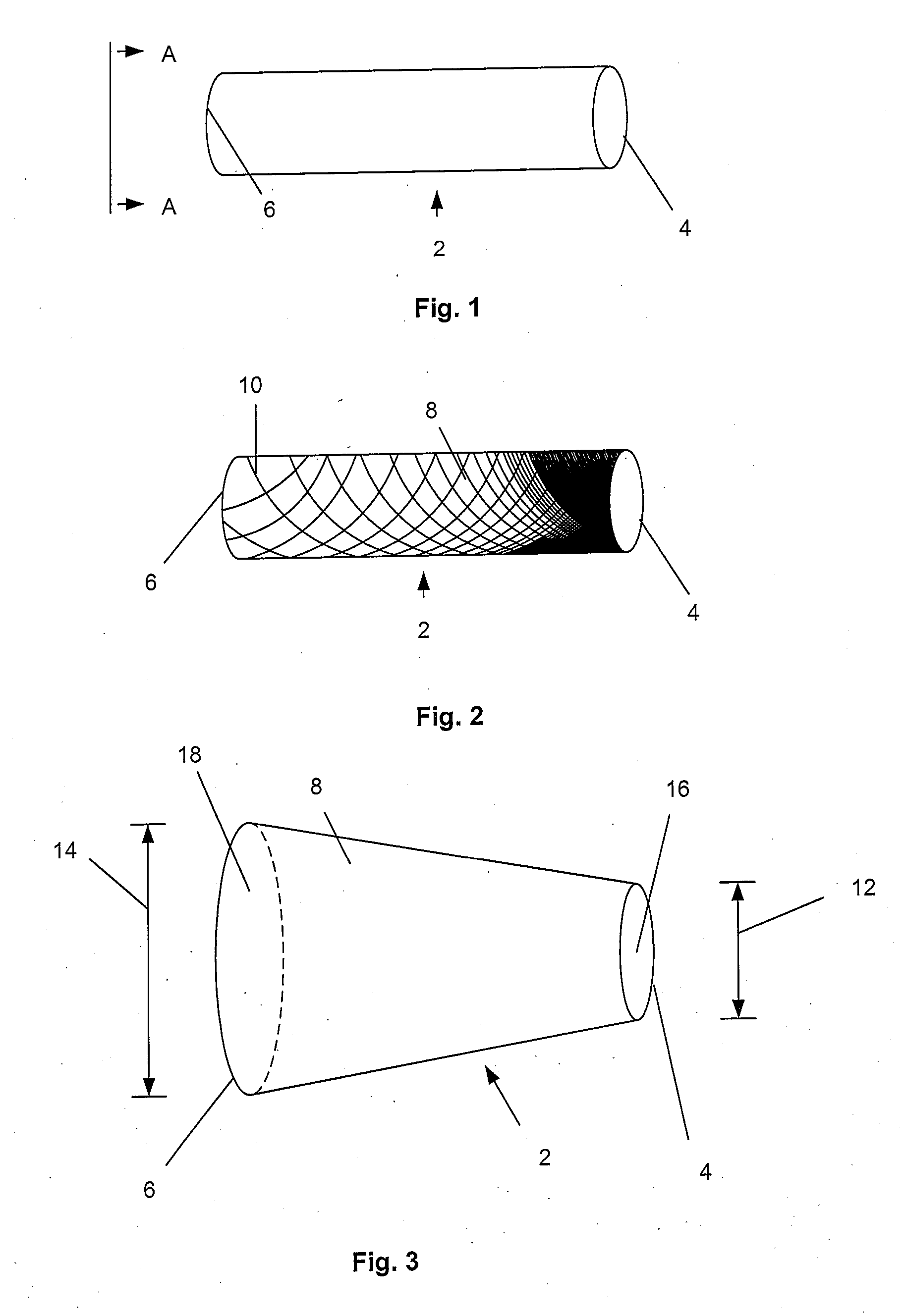
[0114]FIG. 1 illustrates an expandable support device 2, such as a stent, that can be implanted in a bone, such as a compression fracture in a vertebra, in the intervertebral space between two vertebrae, or in soft tissue, such as a herniated intervertebral disc. The expandable support device 2 should be biocompatible. The expandable support device 2 can have one of many configurations, and can be used, for example, for methods of repairing vertebral bone fractures or supporting adjacent vertebral bodies for fusion. The expandable support device 2 can have a first end 4 and a second end 6.

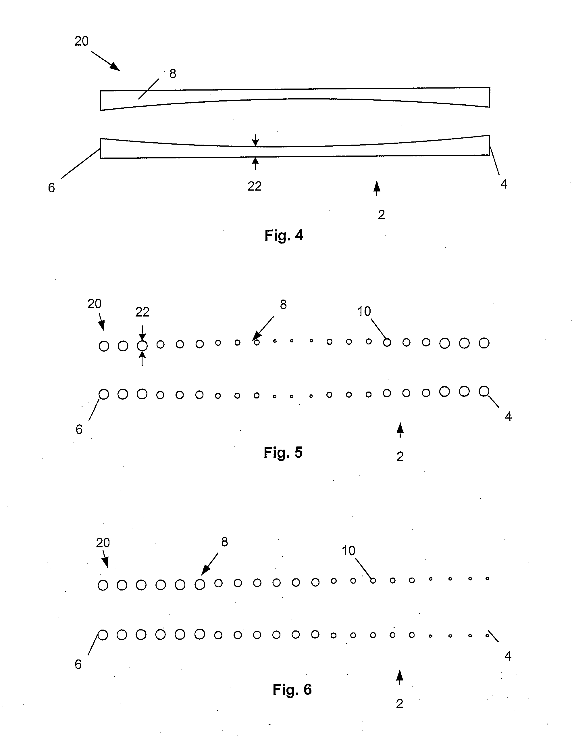
[0115]FIG. 2 illustrates that the expandable support device 2 can have a wall 8. The wall 8 can have struts 10. The struts 10 can vary in density along the length of the expandable support device 2 from the first end 4 to the second end 6. The density of the struts 10 can be higher near the first end 4 than near the second end 6 (as shown). The density of the struts 10 can be higher near the secon...


PUM

PropertyMeasurementUnit
internal pressureaaaaaaaaaa
diameteraaaaaaaaaa

Abstract

An expandable support device for tissue repair is disclosed. The device can be used to repair hard or soft tissue, such as bone or vertebral discs. A method of repairing tissue is also disclosed. The device and method can be used to treat compression fractures. The compression fractures can be in the spine. The device can be deployed by compressing the device longitudinally resulting in radial expansion.

Description

CROSS-REFERENCE TO RELATED APPLICATIONS [0001] This application is a continuation-in-part of PCT Application No. PCT / US2005 / 037126, filed Oct. 12, 2005 which claims priority to U.S. Provisional Application No. 60 / 617,810, filed Oct. 12, 2004; a continuation-in-part of PCT Application No. PCT / US2005 / 034115, filed Sep. 21, 2005, which claims priority to U.S. Provisional Application No. 60 / 612,001, filed Sep. 21, 2004; and a continuation-in-part of PCT Application No. PCT / US2005 / 034742, filed Sep. 26, 2005, which claims priority to U.S. Provisional Application No. 60 / 612,723, filed Sep. 24, 2004, and U.S. Provisional Application No. 60 / 612,724, filed Sep. 24, 2004, all of which are incorporated by reference herein in their entirety. This application also claims the benefit of all of the above-referenced U.S. Provisional applications.BACKGROUND OF THE INVENTION [0002] 1. Field of the Invention [0003] This invention relates to devices for providing support for biological tissue, for exam...

Claims


Application Information

Patent Timeline
Patent Type & Authority Applications(United States)
IPC IPC(8): A61F2/44
CPCA61B17/7098A61F2/4455A61F2/30767A61F2/446A61F2/4611A61F2002/30092A61F2002/30176A61F2002/30579A61F2002/30677A61F2002/30777A61F2002/30785A61F2002/4435A61F2002/444A61F2002/4627A61F2210/0014A61F2230/0054A61F2310/00017A61F2310/00023A61F2310/00029A61F2310/00131A61F2310/00365A61B17/8858A61F2/4425A61F2002/30593
Inventor GREENHALGH, E. SKOTTROMANO, JOHN PAUL
Owner STOUT MEDICAL GROUP
Why Eureka
Try Eureka