Substrate processing apparatus and substrate processing method

a substrate processing and processing apparatus technology, applied in the direction of cleaning processes and apparatus, chemistry apparatus and processes, cleaning using liquids, etc., can solve the problems of increasing the quantity of cold accumulated in the processing space, increasing the temperature of the processing space, and increasing the amount of thermal energy and time required to achieve the effect of improving the process efficiency of the cleaning process

Inactive Publication Date: 2007-09-27
DAINIPPON SCREEN MTG CO LTD
View PDF6 Cites 24 Cited by
  • Summary
  • Abstract
  • Description
  • Claims
  • Application Information

AI Technical Summary

Benefits of technology

[0011]The invention has been made in light of the problems described above, and an object thereof is to provide a substrate processing apparatus and a substrate processing method that are capable of improving the process efficiency of a cleaning process while satisfactorily cleaning a substrate.

Problems solved by technology

However, in the case of executing the cleaning process in the same processing chamber as described above, there have been cases where the following problems occur.
Further, the freezing process is often performed by decreasing the temperature of the processing space to a temperature below the freezing point of the liquid forming the liquid film and, in such cases, the quantity of cold accumulated in the processing space increases.
Therefore, upon defrosting the frozen film, considerable amounts of thermal energy and time have been needed to increase the temperature of the processing space.
This leads not only to poor thermal energy efficiency, but also to difficulty to stabilize the temperature of the processing space to those suitable for the respective freezing process and defrosting process.
Furthermore, such a problem becomes more notable as the volume of the processing space increases particularly as in the case where a plurality of substrates are accommodated in the processing space, and has been a big obstacle in improving the process efficiency of the cleaning process.

Method used


Image

  • Substrate processing apparatus and substrate processing method
  • Substrate processing apparatus and substrate processing method
  • Substrate processing apparatus and substrate processing method

Examples


first embodiment

[0040]A. Overall Construction of Substrate Processing Apparatus

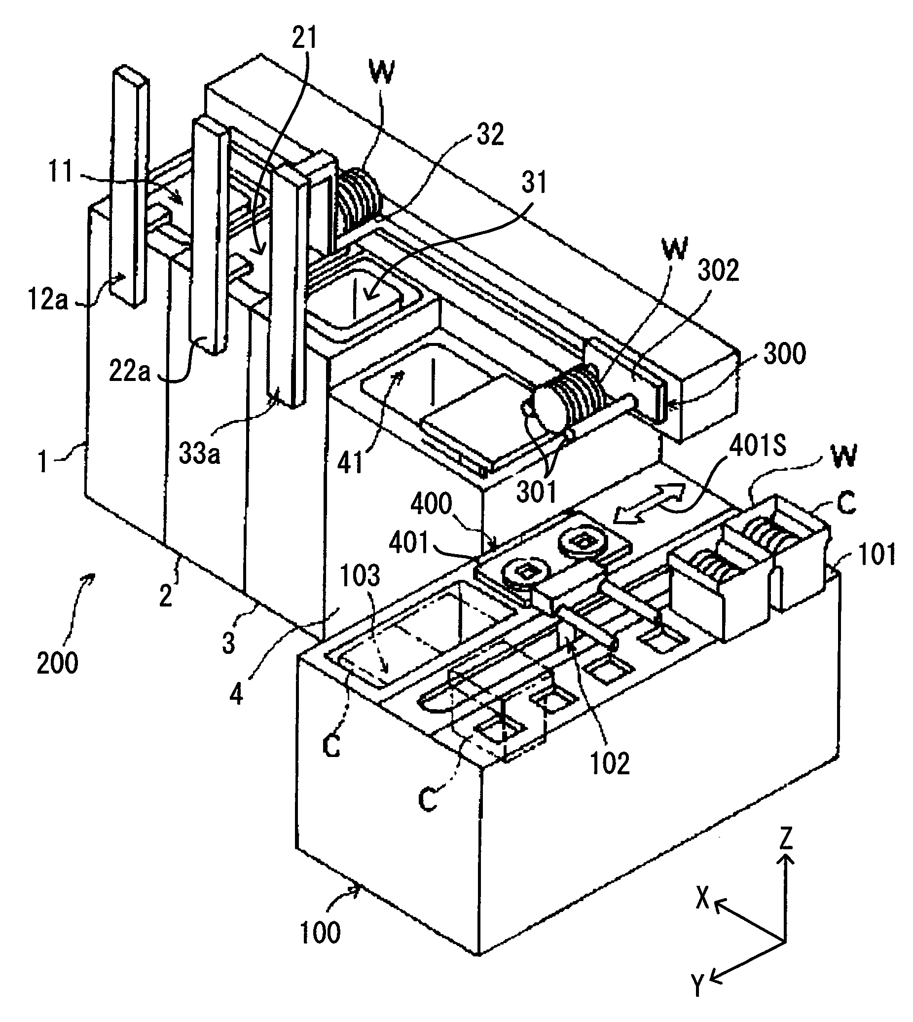
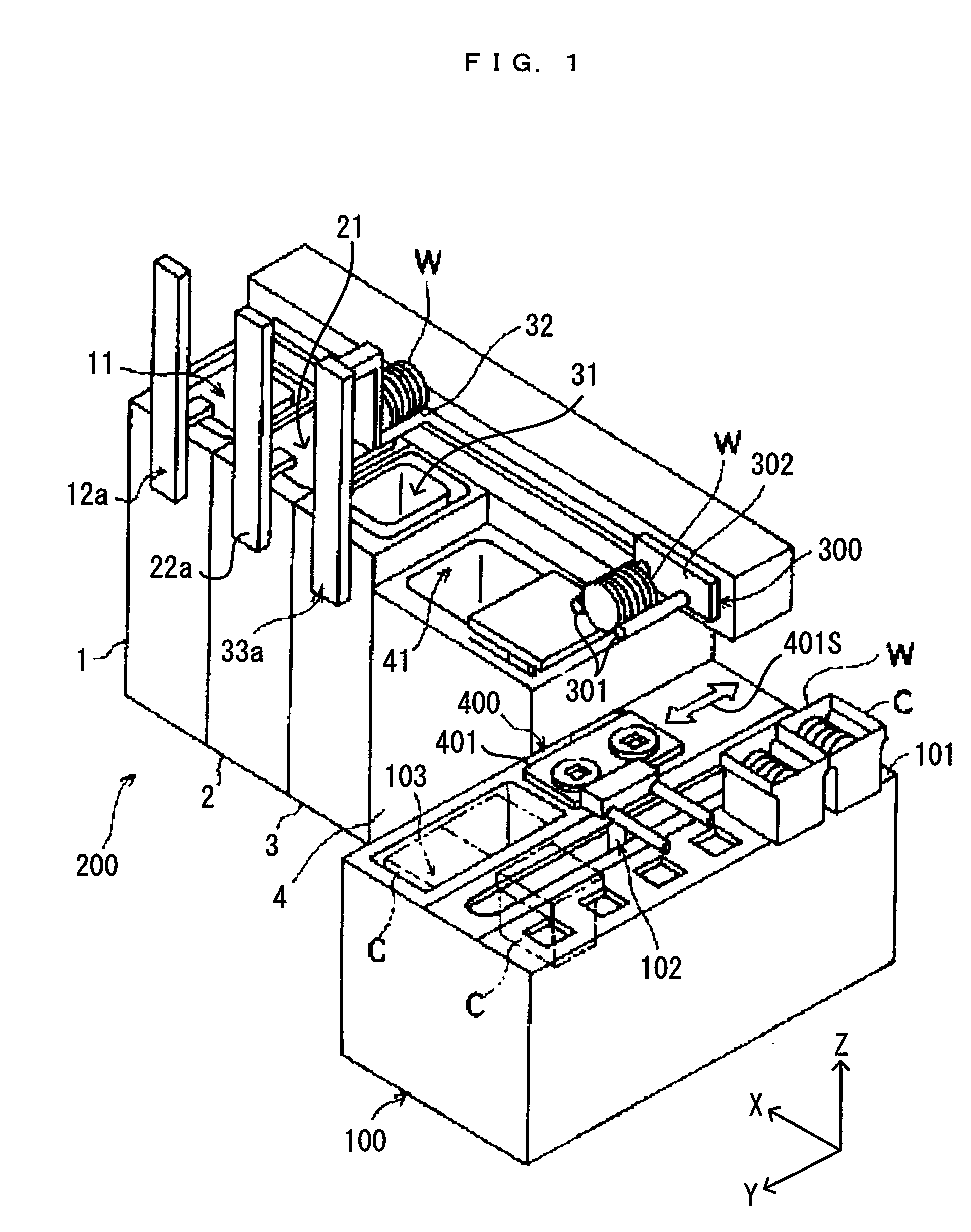
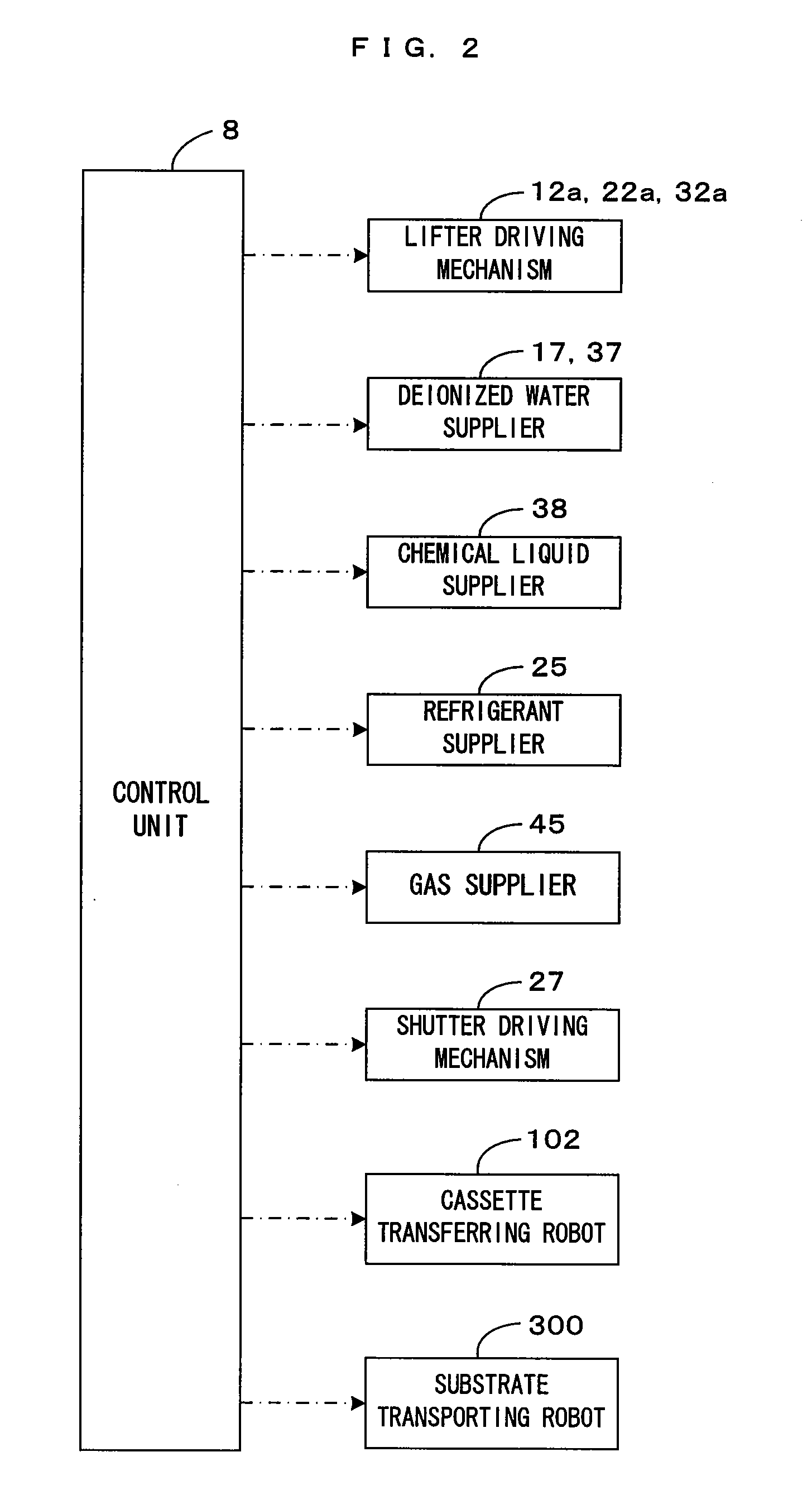
[0041]FIG. 1 is a perspective view showing a first embodiment of a substrate processing apparatus according to the present invention, and FIG. 2 is a block diagram showing a main control construction of the substrate processing apparatus shown in FIG. 1. This substrate processing apparatus is a batch type substrate processing apparatus that is used for the cleaning processes for the purpose of removing contaminants such as particles and various types of metallic impurities adhering to surfaces (corresponding to “surface-to-be-processed” in the invention) of substrates W such as semiconductor wafers. More specifically, this is an apparatus which removes contaminants together with frozen films by applying preprocessing liquid to the substrate surfaces, on which device patterns are formed, to thereby form films of the preprocessing liquid, and then freezing the liquid films and supplying post-processing liquid to the liquid...

modification to first embodiment

[0081]It should be appreciated that the present invention is not limited to the above first embodiment and various other modifications can be made without departing from the spirit of the present invention. For example, in the above first embodiment, the preprocessing unit 1 forms the liquid films on the surfaces of a plurality of substrates W by immersing the respective substrates W into the preprocessing liquid stored in the processing tank 11 and then pulling the substrates W up. However, the liquid film forming method is not limited to this. The preprocessing liquid may be showered to the substrate surfaces, for example, as shown in FIG. 7 to form liquid films on the substrate surfaces.

[0082]FIG. 7 is a diagram showing a modification of the preprocessing unit. This preprocessing unit 1A includes shower nozzles 52 near the top of a processing tank 51. Two shower nozzles 52 are disposed at the opposite sides of the substrates W accommodated in a processing tank 51, and are formed ...

second embodiment

[0102]Further, in the above first embodiment, although the transporting mechanism such as the substrate transporting robot collectively loads a plurality of substrates W into the post-processing unit after collectively unloading the substrates W subjected to the freezing process from the freezing unit, the present invention is not limited to this. For example, the transporting mechanism may load the substrates W subjected to the freezing process one by one into a wet processing unit that functions as the post-processing unit after unloading them one by one from the freezing unit. Second to fifth embodiments having such a construction are described below.

[0103]FIG. 11 is a plan layout diagram of a substrate processing apparatus of a second embodiment. FIG. 12 is a block diagram showing a main control construction of the substrate processing apparatus shown in FIG. 11. In this substrate processing apparatus, a wet processing unit 10 and a freezing unit 20 are arranged while being sepa...


PUM


Abstract

Substrates having liquid films with preprocessing liquid on surfaces thereof in a preprocessing unit are transported to a freezing unit arranged separately from the preprocessing unit by a substrate transporting robot. In the freezing unit, the substrates are accommodated in a processing space in a processing chamber and the liquid films are frozen by decreasing the temperature of the processing space to a temperature below the freezing point of the preprocessing unit. Subsequently, the substrates subjected to the freezing process are transported from the freezing unit to a post-processing unit arranged separately from the freezing unit. In the post-processing unit, cleaning liquid is supplied to frozen films, whereby contaminants having adhesive forces to the substrate reduced by the freezing process can be easily removed together with the frozen film.

Description

CROSS REFERENCE TO RELATED APPLICATION[0001]The disclosure of Japanese Patent Applications enumerated below including specification, drawings and claims is incorporated herein by reference in its entirety:[0002]No. 2006-82085 filed Mar. 24, 2006; and[0003]No. 2006-343960 filed Dec. 21, 2006.BACKGROUND OF THE INVENTION[0004]1. Field of the Invention[0005]The present invention relates to a substrate processing apparatus and a substrate processing method for cleaning substrates of various types (hereinafter called simply “substrates”) such as semiconductor wafers, glass substrates for photomasks, glass substrates for liquid crystal displays, glass substrates for plasma displays and substrates for optical disks.[0006]2. Description of the Related Art[0007]With the miniaturization, higher functionalization and higher precision of devices typified by semiconductor devices, it becomes increasingly difficult to remove fine contaminants such as foreign substances and particles adhering to a ...

Claims


Application Information

Patent Timeline
Patent Type & Authority Applications(United States)
IPC IPC(8): B08B3/00
CPCH01L21/02041H01L21/67051H01L21/68742H01L21/67109H01L21/67309H01L21/67057
Inventor IZUMI, AKIRAMATSUBARA, HIDEAKIFUJIWARA, NAOZUMIMIYA, KATSUHIKO
Owner DAINIPPON SCREEN MTG CO LTD
Why Eureka
Try Eureka