Photovoltaic conversion cell, photovoltaic conversion module, photovoltaic conversion panel, and photovoltaic conversion system

a photovoltaic conversion and photovoltaic conversion technology, applied in the direction of basic electric elements, electrical apparatus, semiconductor devices, etc., can solve the problems of weak light scattering, reduced short-circuit current, and difficulty in further reinforcement of light reflection in back face electrodes configured by transparent conductive films and metallic layers, so as to increase the effect of increasing the photovoltaic conversion efficiency

Inactive Publication Date: 2007-09-27
MITSUBISHI HEAVY IND LTD
View PDF4 Cites 23 Cited by
  • Summary
  • Abstract
  • Description
  • Claims
  • Application Information

AI Technical Summary

Benefits of technology

[0030]The photovoltaic conversion cell, the photovoltaic conversion module, the photovoltaic conversion panel, and the photovoltaic conversion system of the present invention have an effect of increasing the photovoltaic conversion efficiency.
[0031]More specifically, the photovoltaic conversion cell, the photovoltaic conversion module, the photovoltaic conversion panel, and the photovoltaic conversion system of the present invention, as a result of a reduction in the amount of the electromagnetic waves that penetrate and are absorbed by the back face electrode layer in a thin film Si (Silicon) solar battery (photovoltaic conversion cell), have an effect of increasing the photovoltaic conversion efficiency.

Problems solved by technology

However, in regard to thin film Si photovoltaic conversion cells in which a-textured structure is not used, the light scattering is weak, and the short-circuit current decreases.
Accordingly, further reinforcement of light reflection in back face electrodes configured by a transparent conductive film and a metallic layer is difficult, and it is difficult to increase the photovoltaic conversion efficiency.

Method used


Image

  • Photovoltaic conversion cell, photovoltaic conversion module, photovoltaic conversion panel, and photovoltaic conversion system
  • Photovoltaic conversion cell, photovoltaic conversion module, photovoltaic conversion panel, and photovoltaic conversion system
  • Photovoltaic conversion cell, photovoltaic conversion module, photovoltaic conversion panel, and photovoltaic conversion system

Examples


first embodiment

[0052]Hereinbelow, the best mode for implementing the photovoltaic conversion cell of a first embodiment according to the present invention is explained with reference to the drawings.

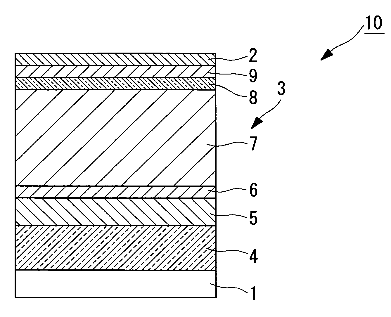
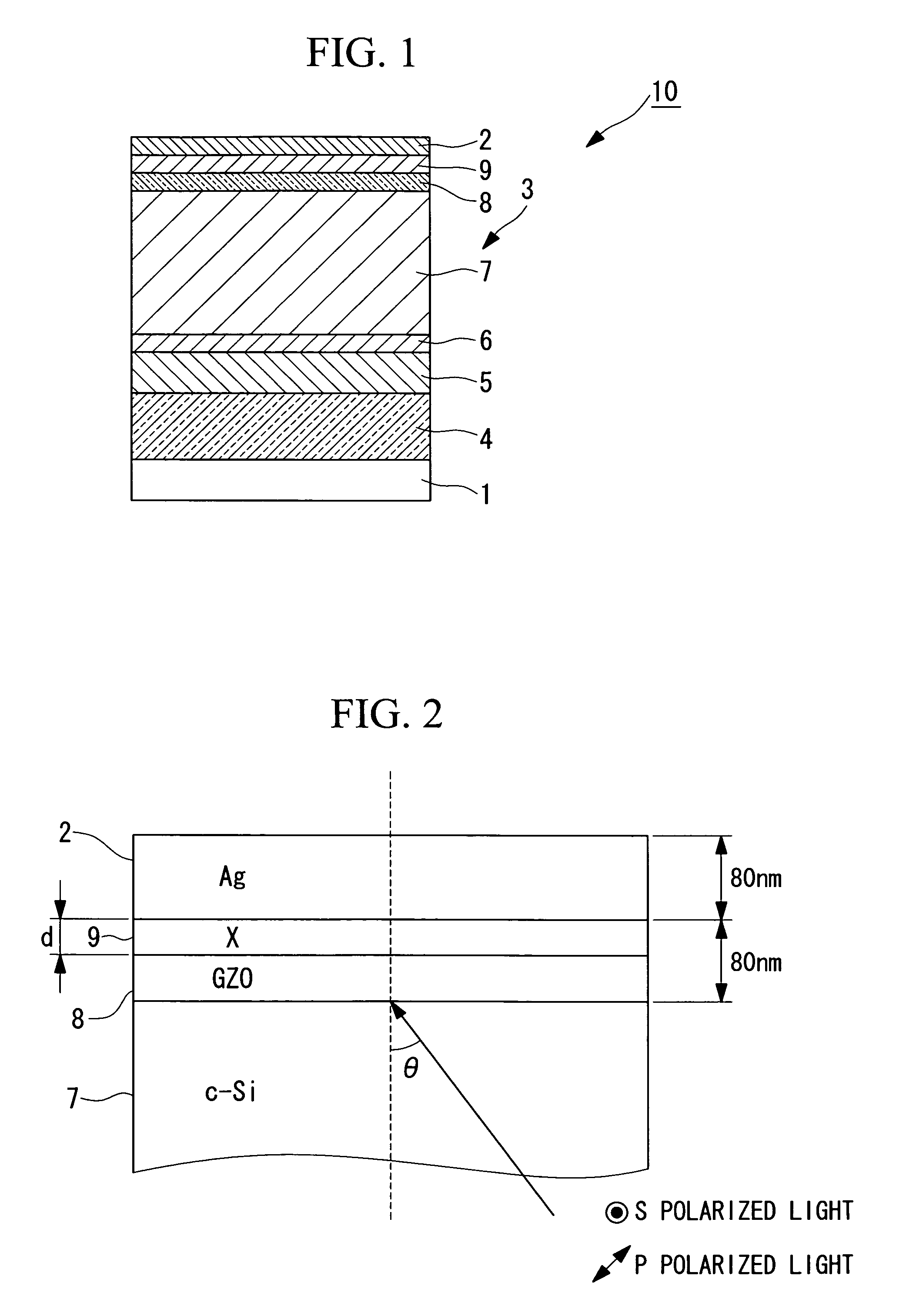
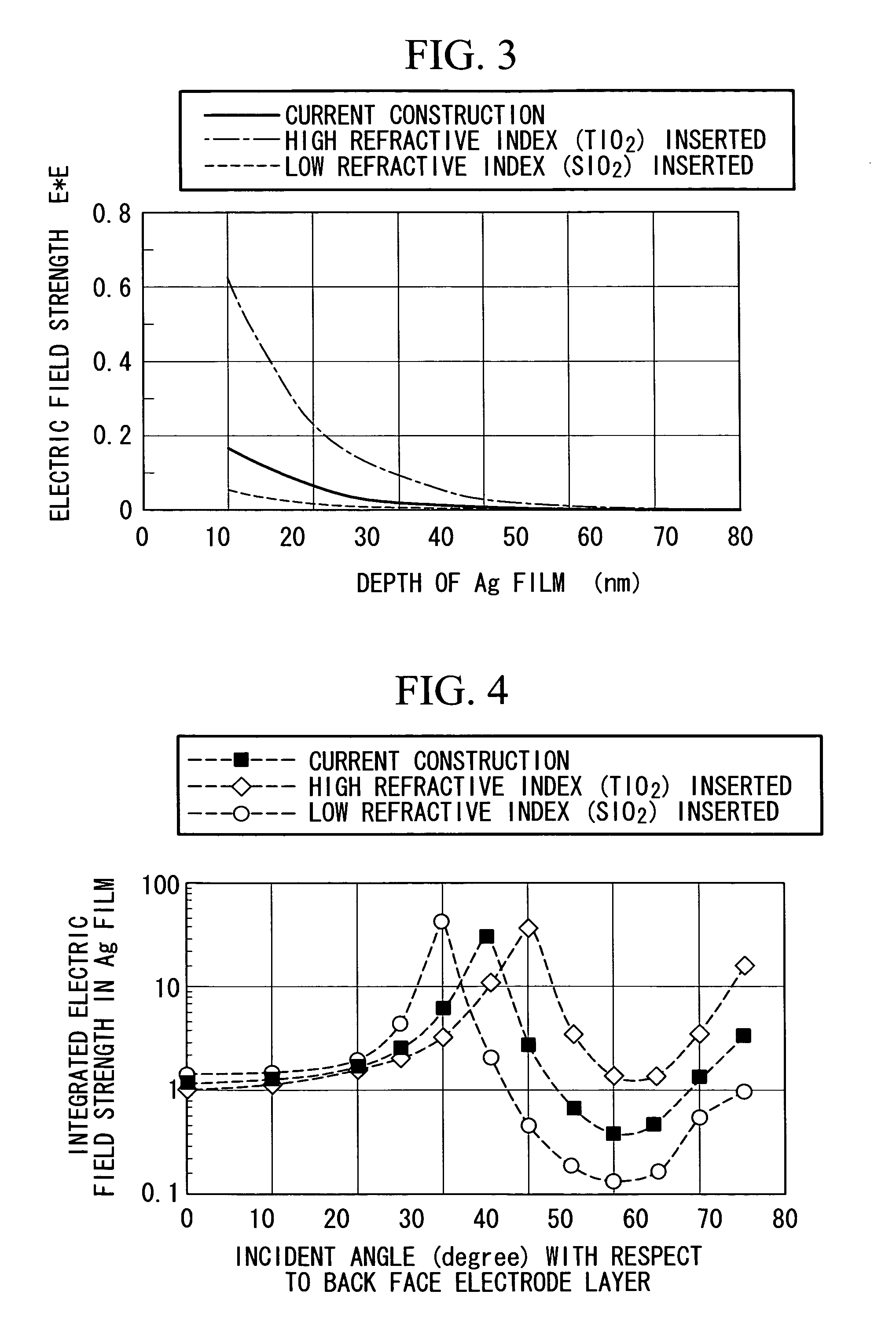
[0053]Referring to FIG. 1, a cross-sectional view of the photovoltaic conversion cell is shown. In regard to the photovoltaic conversion cell 10, a multilayered power generation layer 3 is formed between a light incident side glass substrate (transparent substrate) 1 and a back face non-transparent electrode (back face electrode layer) 2. The power generation layer 3 is formed as a six layered lamination structure comprising a first transparent (optically transparent) conductive layer 4, a top cell layer (second photovoltaic conversion layer) 5 which is a photovoltaic conversion layer, a middle layer 6 which is a transparent conductive film, a bottom cell layer (first photovoltaic conversion layer) 7 which is a photovoltaic conversion layer, a second transparent conductive film (transparent layer, uppe...

second embodiment

[0111]Hereinbelow, a photovoltaic conversion module furnished with the photovoltaic conversion cell of a second embodiment according to the present invention is explained.

[0112]FIG. 16 is a drawing explaining the configuration of the photovoltaic conversion module in the present embodiment.

[0113]The photovoltaic conversion module 120 is, as shown in FIG. 16, multiply provided with a plurality of photovoltaic conversion cells 110 on a sheet of glass substrate 101, and is one in which the plurality of photovoltaic conversion cells 110 are electrically connected in series. The photovoltaic conversion cells 110 are furnished with a first transparent conductive film 104, a photovoltaic conversion layer (first photovoltaic conversion layer) 107, a second transparent conductive film (transparent layer, upper portion transparent layer) 108, a refractive index adjustment layer (transparent layer) 109, and a back face non-transparent electrode (back face electrode layer) 102.

[0114]The first t...

third embodiment

[0124]Hereinbelow, a photovoltaic conversion panel furnished with the photovoltaic conversion module according to a third embodiment of the present invention is explained.

[0125]FIG. 17 is a drawing explaining the configuration of the photovoltaic conversion panel according to the present embodiment.

[0126]The photovoltaic conversion panel 201 is furnished with, as shown in FIG. 17, the photovoltaic conversion module 120 according to the second embodiment, a coating film 203, a frame body 205, wiring 207, and a terminal box (wiring) 209.

[0127]The coating film 203 is a laminate film that protects the face on the back face non-transparent electrode 102 side in the photovoltaic conversion module 120. The frame body 205 covers the surroundings of the photovoltaic conversion module 120, and supports the photovoltaic conversion module 120. The wiring 207 leads the electrical power generated in the photovoltaic conversion module 120 to the terminal box 209. In regard to the wiring 207, one t...


PUM


Abstract

The efficiency of a thin film Si solar battery is improved. Between a back face electrode and a transparent conductive film provided on a front face side of the back face electrode, a refractive index adjustment layer is interposed made from a material that has a lower refractive index than that of the transparent conductive film. For example when the transparent conductive film is GZO, SiO2 is interposed between the transparent conductive film and the back face electrode made from Ag. As a result light that penetrates into and is absorbed at the back face electrode is reduced, and the reflectivity of light at the back face electrode is improved.

Description

BACKGROUND OF THE INVENTION[0001]1. Field of the Invention[0002]The present invention relates to technology that increases the efficiency of photovoltaic conversion cells, photovoltaic conversion modules, photovoltaic conversion panels, and photovoltaic conversion systems.[0003]This application is based on Japanese Patent Application No. 2006-00156, the content of which is incorporated herein by reference.[0004]2. Description of Related Art[0005]In Japanese Unexamined Patent Application, Publication No. Hei 5-110125, in regard to a photovoltaic element having a transparent conducting layer between a back face electrode provided on the opposite side to the light incidence face and a photovoltaic conversion layer comprising a semiconductor, there is disclosed a photovoltaic element characterized in that an element that changes electrical conductivity is included in the transparent conducting layer, and the added quantity of the element varies in the direction of film thickness. From p...

Claims


Application Information

Patent Timeline
Patent Type & Authority Applications(United States)
IPC IPC(8): H01L31/00
CPCH01L31/0236H01L31/056Y02E10/52
Inventor SAKAI, SATOSHIKOBAYASHI, YASUYUKIGOYA, SANEYUKINAKANO, YOUJI
Owner MITSUBISHI HEAVY IND LTD
Why Eureka
Try Eureka