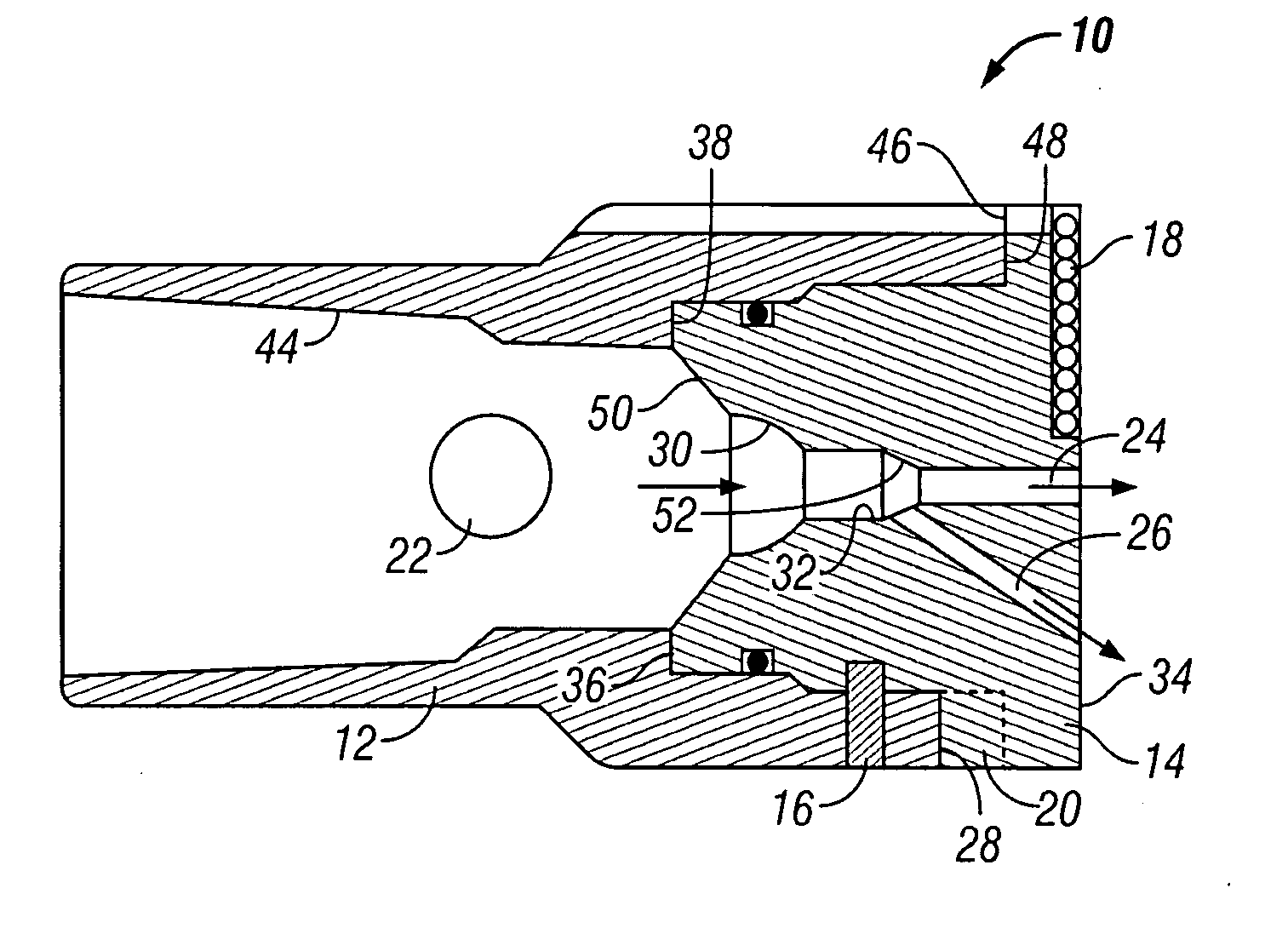
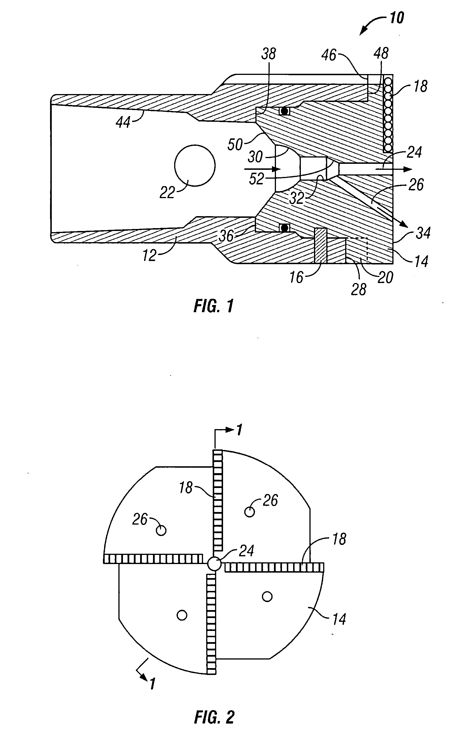
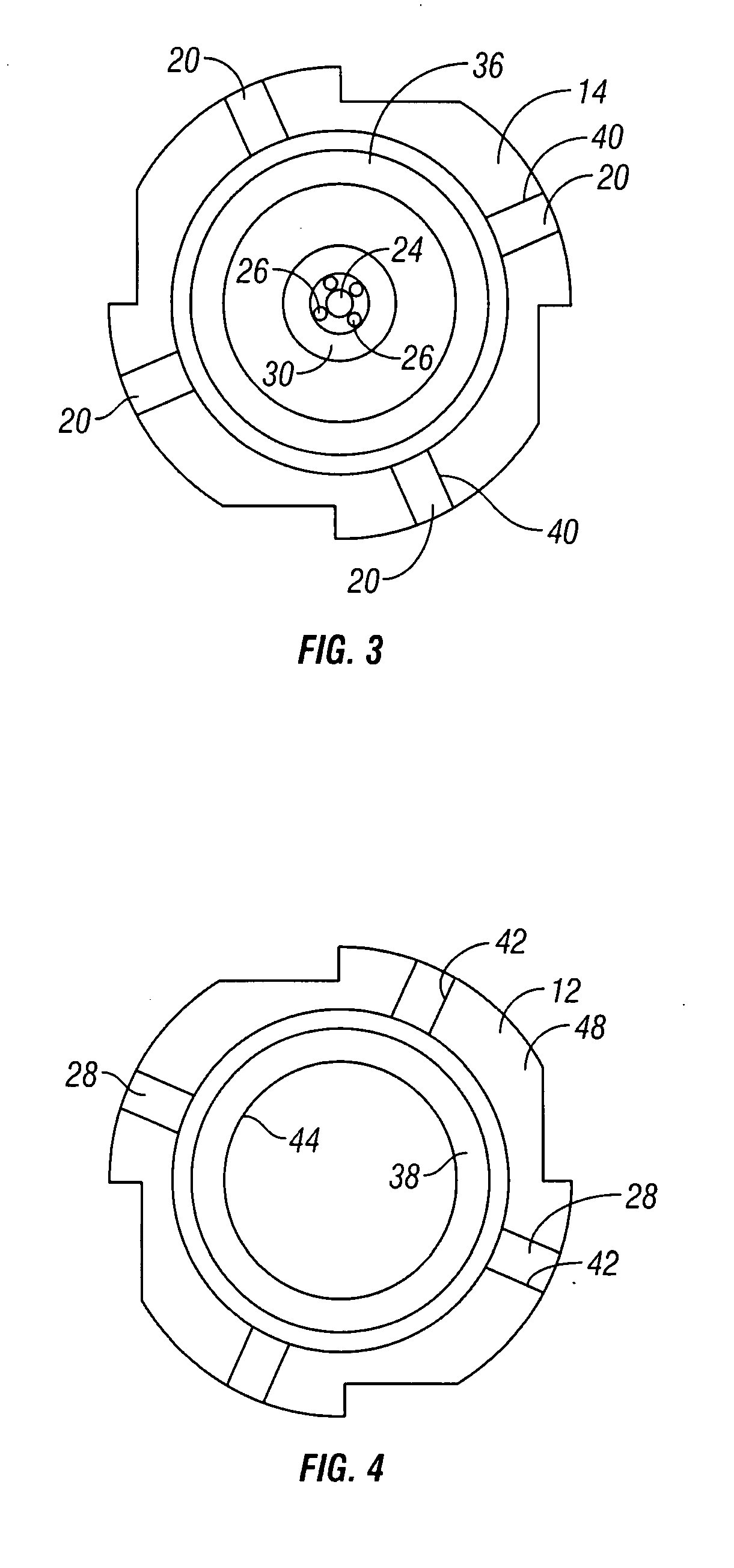
Releasable mill
a releasable mill and milling machine technology, applied in the direction of drilling casings, drilling pipes, borehole/well accessories, etc., can solve the problems of time-consuming and expensive process of tripping a work string into or out of a well, and the passageways are not large enough to provide the desired degree of access to the lower formation
- Summary
- Abstract
- Description
- Claims
- Application Information
AI Technical Summary
Benefits of technology
Problems solved by technology
Method used
Image
Examples
second embodiment
[0030] the milling head is shown in FIG. 6. This embodiment of the milling head 140 can be fitted with a check valve comprising a ball seat 142, a check ball 144, and a spring 146. It can be seen that, as milling fluid passes downhole through the fluid path in the milling head 140, the check ball 144 can be lifted off its seat 142, against the bias of the spring 146, to allow flow out the lower end of the work string. A kick or pressure excursion sometimes occurs in the formation fluids, which could create an undesirable flow in the uphole direction through the work string. To prevent this, the spring 146 biases the check ball 144 toward engagement with its seat 142. As pressure below the milling head 140 increases above the drilling fluid pressure, this causes the check ball 144 to seat more securely, thereby preventing flow in the uphole direction.
third embodiment
[0031] the apparatus 210 of the present invention is shown in FIGS. 7 and 8. In this embodiment, the mill body 212 is secured to the milling head 214 by shear pins 216 in shear pin bores 224 and 226 in the mill body 212 and the milling head 214, respectively. Flow passages 228 are provided through the milling head 214. However, in this embodiment, the check valve comprises a swing check type valve, with a check valve body 262 assembled in the milling head 214, and with a flapper valve 264, which is pivotably mounted to the check valve body 262 by a pivot pin 266. The check valve body 262 can be retained in the milling head 214 by one or more snap rings or pins, as is known in the art. The flapper valve 264 is biased toward the closed position by a spring. Flow of fluid down through the apparatus can open the flapper valve 264 against the spring bias, but backflow through the check valve is prevented by shutting of the flapper valve 264, which seats against the lower side of the chec...
first embodiment
[0032] Also provided in this embodiment is a fishing neck 260, which is retained in the milling head 214, above the check valve body 262, by one or more snap rings or pins, as is known in the art. A ball seat 230 is provided in the upper side of the check valve body 262. When milling has been completed, and it is desired to release the milling head 214 from the mill body 212, a ball 222 is pumped downhole through the work string, to seat in the ball seat 230. Increasing pressure above the pumpable ball 222 then shears the shear pins 216, releasing the milling head 214 from the mill body 212, as in the If it is desired to subsequently remove the milling head 214 from the well bore, known fishing techniques can be used to attach to the fishing neck 260 and pull the milling head 214.
PUM
 Abstract
Description
Claims
Application Information
 - R&D
- Intellectual Property
- Life Sciences
- Materials
- Tech Scout
- Unparalleled Data Quality
- Higher Quality Content
- 60% Fewer Hallucinations
Browse by: Latest US Patents, China's latest patents, Technical Efficacy Thesaurus, Application Domain, Technology Topic, Popular Technical Reports.
© 2025 PatSnap. All rights reserved.Legal|Privacy policy|Modern Slavery Act Transparency Statement|Sitemap|About US| Contact US: help@patsnap.com


