Hydraulic steering

a technology of hydraulic steering and steering valve, which is applied in the direction of steering parts, steering controls, alternative steering control, etc., can solve the problems of small displacement of steering valve, limited by pressure control valve, and steering valve can only be supplied with a certain pressure, so as to achieve the effect of keeping the size of the switching technical design small

Active Publication Date: 2007-09-27
DANFOSS PAUER SOLYUSHENS APS
View PDF19 Cites 12 Cited by
  • Summary
  • Abstract
  • Description
  • Claims
  • Application Information

AI Technical Summary

Benefits of technology

[0011] Preferably, the pilot valve arrangement has solenoid valves, and a control device is provided, with which the solenoid valves and the stop valve can be deenergized. In a similar manner the control device can of course supply the solenoid valves with the corresponding electrical signals for activation of the steering valve, and at the same time open the stop valve by means of a corresponding electrical signal, to ensure the supply of hydraulic fluid to the pilot valve arrangement. As both the pilot valve arrangement and the stop valve can be electrically activated, the switching technical design can be kept relatively small.
[0012] Preferably, in a first switching position the sto

Problems solved by technology

Firstly, the steering valve can only be supplied with a certain pressure, which is set and thus limited by the pressure control valve.
Accordingly, the risk that leakages occur in connection with too high pressures, which could cause a displacement of the steering valve, is relatively small.
The pilot valves can namely no longer let hydraulic pressure reach th

Method used


Image

  • Hydraulic steering
  • Hydraulic steering
  • Hydraulic steering

Examples


Embodiment Construction

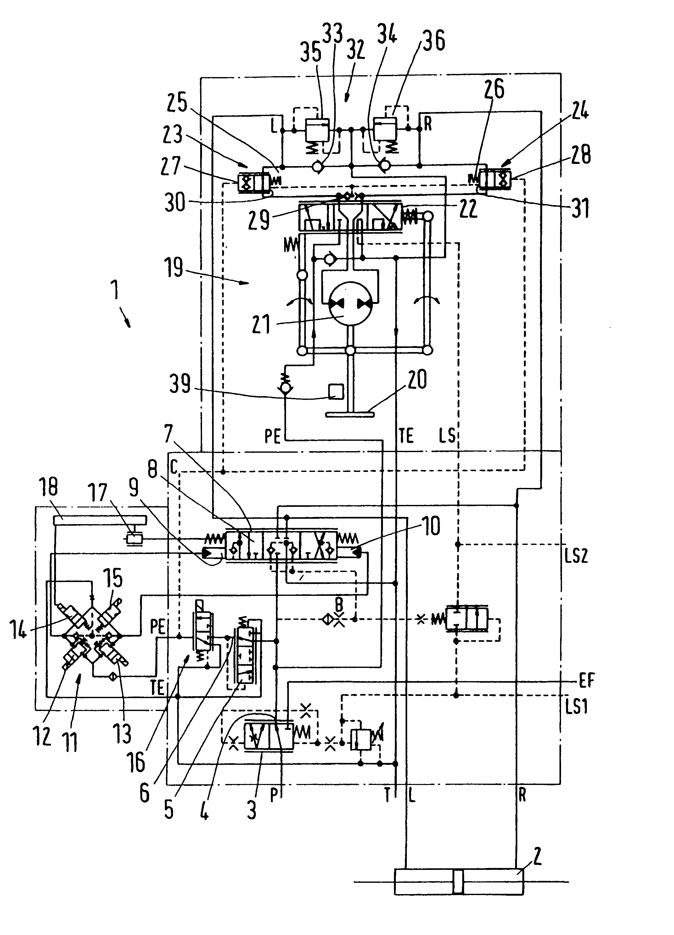
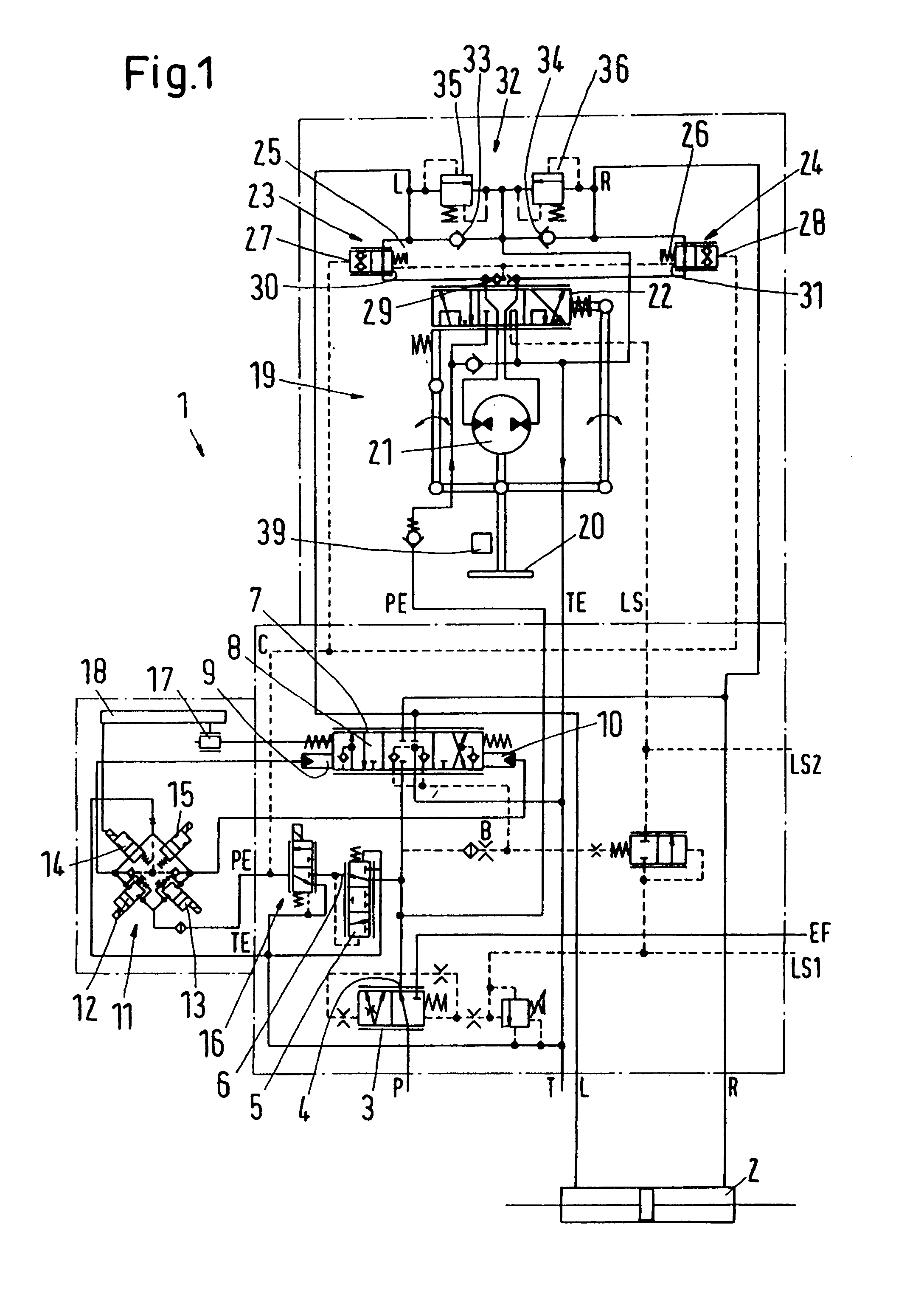
[0028]FIG. 1 shows a hydraulic steering 1 with a steering motor 2 that can be supplied with hydraulic fluid via two working pipes L, R. The hydraulic fluid is supplied via a high-pressure connection P and discharged via a low-pressure connection T. The high pressure connection P is, for example, connected to a pump that is driven by the drive motor of a vehicle, which is equipped with the steering 1. The low pressure connection T is, for example, connected to a tank (not shown in detail).

[0029] First the high-pressure connection P is connected to a priority valve 3 known per se, whose priority outlet 4 is connected to a pressure control valve 5. The outlet 6 of the pressure control valve 5 supplies a pressure of, for example, 12 bar. The priority outlet 4 of the priority valve 3 is further connected to an inlet of a proportionality valve 7 that has a slide 8, which can be displaced by pressures at control connection 9, 10.

[0030] The control connections 9, 10 are connected to a pil...


PUM


Abstract

The invention concerns a hydraulic steering (1) with a steering valve (7) located between a supply connection arrangement (P, T) and a steering motor (2). It is endeavoured to improve the safety of such a steering. For this purpose, the steering valve (7) has a hydraulic drive (9, 10) with a pilot valve arrangement (11) supplied by a pressure control valve (5), a stop valve (16) being located between the pressure control valve (5) and the pilot valve arrangement (11).

Description

CROSS REFERENCE TO RELATED APPLICATIONS [0001] Applicant hereby claims foreign priority benefits under U.S.C. § 119 from German Patent Application No. 10 2006 010 695.4 filed on Mar. 8, 2006, the contents of which are incorporated by reference herein. FIELD OF THE INVENTION [0002] The invention concerns a hydraulic steering with a steering valve located between a supply connection arrangement and a steering motor. BACKGROUND OF THE INVENTION [0003] Such a steering is known from, for example, DE 102 57 130 A1. The steering valve has a valve slide with power assisted activation. When displacing the valve slide, a path from the supply connection arrangement to the steering motor is more or less released, so that the steering motor is activated. [0004] A similar embodiment is shown in the later published German patent application 10 2004 021 351. [0005] When the steering valve is hydraulically activated, leakages inside the steering that cannot be avoided cause the risk that the steerin...

Claims


Application Information

Patent Timeline
IPC IPC(8): B62D5/08
CPCB62D1/22B62D5/093B62D5/09
Inventor KRYHLMAND, ANDERSPEDERSEN, OVEHANSEN, NIELS BJARNEENNEMARK, POUL
Owner DANFOSS PAUER SOLYUSHENS APS
Why Eureka
Try Eureka