Mold for Injection Molding Light Guide Plate and Process for Producing Light Guide Plate Using the Mold

Inactive Publication Date: 2007-09-27
ZEON CORP
View PDF4 Cites 14 Cited by
  • Summary
  • Abstract
  • Description
  • Claims
  • Application Information

AI Technical Summary

Benefits of technology

[0011] As the result of intensive studies by the present inventors to achieve the above object, it was found that, in a mold for injection molding for forming a light guide plate having a face receiving incident light, a face opposite to the face receiving incident light, a face outputting light, a face reflecting light opposite to the face outputting light and two side faces by injection molding of a melted resin material, the object could be achieved by disposing a plurality of pin gates or film gates having a small area at the portion corresponding to the side face of th

Problems solved by technology

However, a product formed by injection molding inevitably has marks formed by a gate, which adversely affects obtaining a uniform face of display due to unevenness in luminance.
However, the above processes have a problem in that the cycle time increases since a step of cutting off the gate portions from the product formed by the molding and, occasiona

Method used


Image

  • Mold for Injection Molding Light Guide Plate and Process for Producing Light Guide Plate Using the Mold
  • Mold for Injection Molding Light Guide Plate and Process for Producing Light Guide Plate Using the Mold
  • Mold for Injection Molding Light Guide Plate and Process for Producing Light Guide Plate Using the Mold

Examples


example 1

[0074] A light guide plate was prepared in accordance with the injection molding using a resin having an alicyclic structure [manufactured by NIPPON ZEON Co., Ltd.; ZEONOR 1060R].

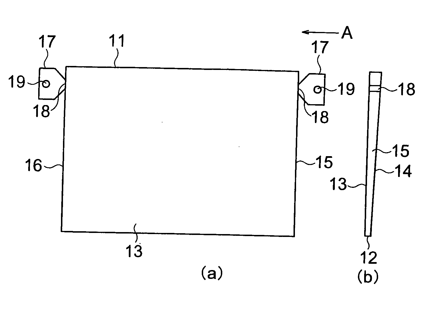
[0075] A mold which had a length of the shorter edge of 220 mm, a length of the longer edge of 290 mm, a thickness of the side face at the side of the longer edge corresponding to the face receiving incident light of 2.2 mm, a thickness of the side face at the side of the longer edge corresponding to the face opposite to the face receiving incident light of 0.7 mm, film gates having a width of 25 mm and a thickness of 0.3 mm formed on the both side faces at the side of the shorter edge each at the position separated from the face receiving incident light by 5 mm and a room for balancing flow having a volume of 1,200 mm3 such as that shown in FIG. 5, was used.

[0076] When the area of the gate was represented by S′ (mm2), the area of the side face of the light guide plate was represented by A (mm2), the leng...

example 2

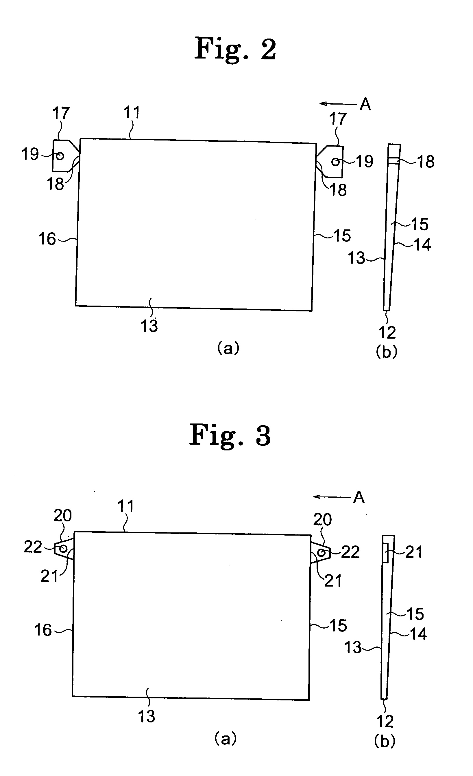
[0079] A light guide plate was prepared in accordance with the same procedures as those conducted in Example 1 except that a mold which had a length of the shorter edge of 220 mm, a length of the longer edge of 290 mm, a thickness of the side face at the side of the longer edge corresponding to the face receiving incident light of 2.2 mm, a thickness of the side face at the side of the longer edge corresponding to the face opposite to the face receiving incident light of 0.7 mm, pin gates having a thickness of 2 mm, a width of 1 mm and a length of the gate land of 0.5 mm formed on both side faces at the side of the shorter edge each at the position separated from the face receiving incident light by 20 mm and a room for balancing flow having a volume of 1,350 mm3 such as that shown in FIG. 4, was used. The obtained light guide plate had no sink marks, and the condition of transcription was good over the entire face.

[0080] When the area of the gate was represented by S (mm2), the ar...

example 3

[0081] A light guide plate was prepared in accordance with the same procedures as those conducted in Example 1 except that a methacrylic resin [manufactured by ASAHI KASEI Co., Ltd.; DELPET 70NHX] was used in place of the resin having an alicyclic structure. The obtained light guide plate had no sink marks, and the condition of transcription was good over the entire face. Warp arose when the cooling time was 27 seconds. The cooling time was extended to 32 seconds, and a light guide plate having no warp was obtained. The cycle time was 45 seconds. The results of evaluations are shown in Table 1.


PUM

PropertyMeasurementUnit
Temperatureaaaaaaaaaa
Timeaaaaaaaaaa
Areaaaaaaaaaaa

Abstract

Molds for injection molding a light guide plate in which a plurality of pin gates and/or film gates for injecting a melted resin material for molding into the cavity portion are formed at portions corresponding to the side portions of the product, a room for balancing flow having an ear shaped portion to which the material is supplied is disposed between each gate and a sprue or a runner, and the area of each gate is set so that the temperature of the material introduced into the cavity is higher than that supplied to each room by at least 5° C. due to heat generated from shearing when the material passes through the gate; and a process for producing a light guide plate using the molds. Formation of weld lines, sink marks, flow marks and warp is suppressed, and a product exhibiting excellent quality without the necessity of steps of gate cutting and finishing can be obtained.

Description

TECHNICAL FIELD [0001] The present invention relates to a mold for injection molding a light guide plate and a process for producing a light guide plate using the mold. More particularly, the present invention relates to a mold for injection molding a light guide plate suppressing formation of weld lines, sink marks, flow marks and warp and providing a product of injection molding exhibiting excellent quality without the necessity of steps of gate cutting and finishing and a process for producing a light guide plate using the mold. BACKGROUND ART [0002] Liquid crystal display devices are widely used for personal computers, flat panel televisions and panels for carnavigations. As the back light device for liquid crystal display devices, the back light device of the edge light type in which a tubular light source is placed in the edge portion of a light guide plate and the back light device of the direct type in which a tubular light source is placed directly under the face of display...

Claims


Application Information

Patent Timeline
IPC IPC(8): B29D11/00B29C45/26B29C45/27F21V8/00G02B6/00
CPCB29C45/2708G02B6/0065G02B6/0046B29C45/26B29C45/18G02B6/00
Inventor HAYASHI, MASAHIKOUEKI, KAZUNORITAZAKI, SATOSHIOBUCHI, KAZUYUKI
Owner ZEON CORP
Why Eureka
Try Eureka