Flexible Electroluminescent Devices

a light-emitting device and flexible technology, applied in the field of organic light-emitting devices, can solve the problems of short life of devices, oleds formed on ultrathin glass sheets have limited potential as flexible light-emitting displays, and ultra-brittle sheets, etc., to achieve the effect of reducing oxygen and moisture permeation, high flexibility, and superior barrier properties

Inactive Publication Date: 2007-09-27
AGENCY FOR SCI TECH & RES
View PDF20 Cites 89 Cited by
  • Summary
  • Abstract
  • Description
  • Claims
  • Application Information

AI Technical Summary

Benefits of technology

[0007] The present invention is directed to a flexible organic light emitting diode (OLED), and more specifically, a polymer light emitting diode (PLED), which is formed on an opaque flexible substrate. The opaque flexible substrate is composed of one of the following: (i) a plastic layer laminated to or coated with a metal layer, (ii) a metal layer sandwiched between two plastic layers, or (iii) a metal foil. When the OLED is formed on a metal surface of the flexible substrate, the metal surface may be coated with an isolation layer. The isolation layer may be a spin-coated polymer layer or a dielectric layer. The metal in the flexible substrate serves as a barrier to minimize the permeation of oxygen and moisture to the OLED. In addition, the OLED of the present invention is provided with a transparent or semi-transparent upper electrode so that light can be emitted through the upper electrode. The novel design of the present invention yields an OLED having superior barrier properties and high flexibility, which can be easily fabricated by mass production.

Problems solved by technology

Ultrathin glass sheets, however, are very brittle and OLEDs formed on ultrathin glass sheets have limited potential as flexible OLED displays.
However, these devices have very short lifetimes because plastics exhibit low resistance to water and oxygen.
These approaches, however, require numerous deposition steps and potentially produce some adverse effects on the optical and mechanical performance of the OLEDs.
Thus, these approaches cannot resolve the permeation problem in a cost-effective way.

Method used


Image

  • Flexible Electroluminescent Devices
  • Flexible Electroluminescent Devices
  • Flexible Electroluminescent Devices

Examples


Embodiment Construction

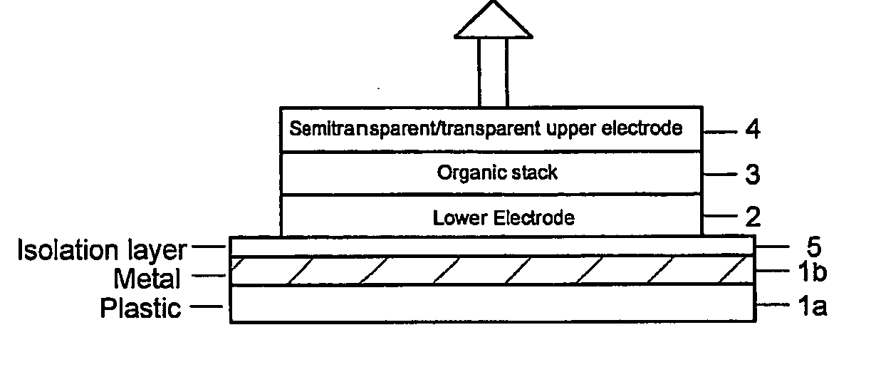
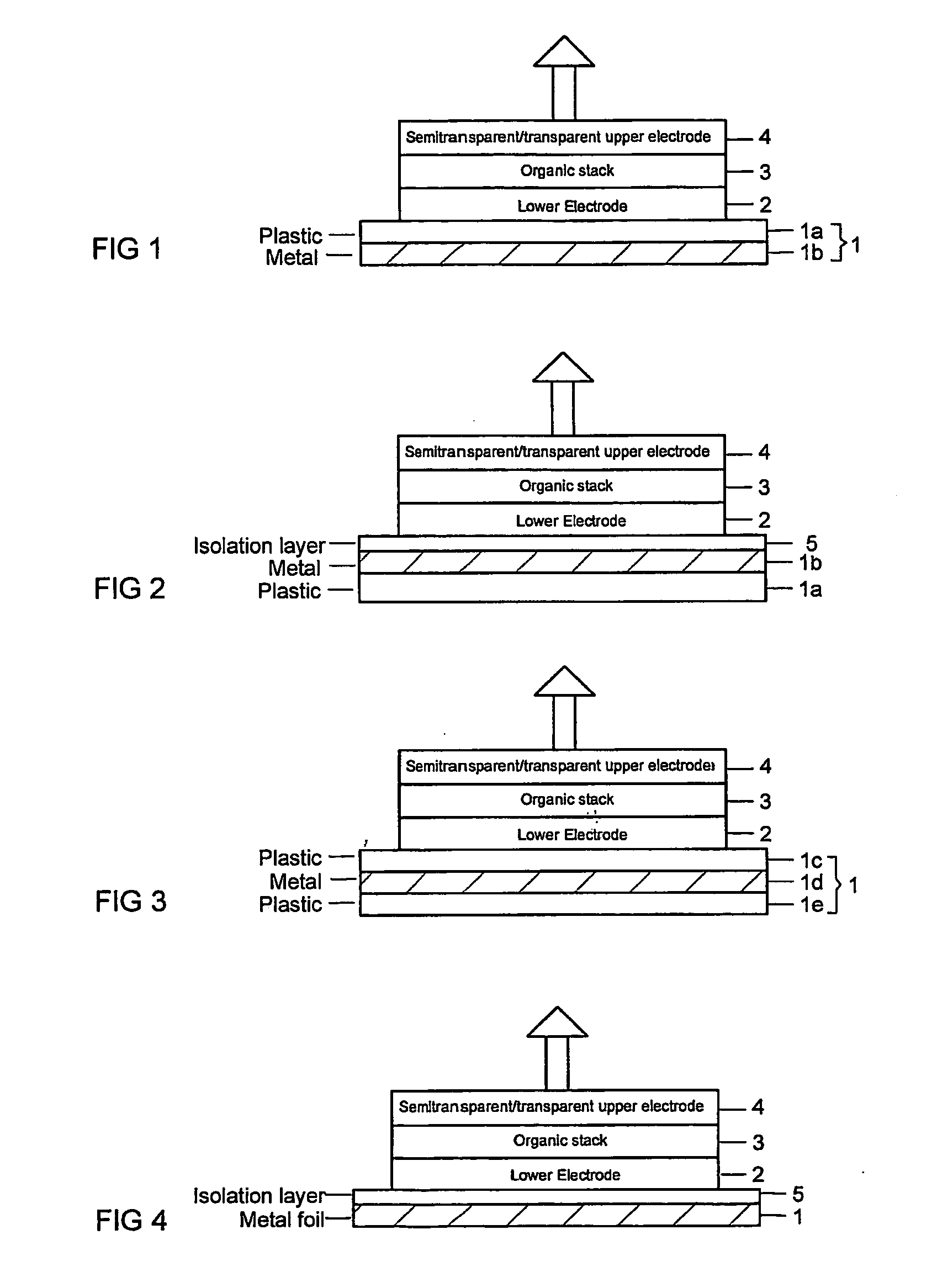
[0014] Referring to FIG. 1, the representative OLED of the present invention comprises a flexible opaque substrate 1, a lower electrode 2 on top of the substrate, an organic stack 3 on top of the lower electrode, and a semi-transparent or transparent upper electrode 4 on top of the organic stack. In one embodiment, the flexible opaque substrate 1 is composed of a plastic layer 1a laminated to or coated with a metal layer 1b as shown in FIG. 1. Alternatively, it is also feasible to form the OLED on the metal side of the substrate 1 as shown in FIG. 2. In such a case, it may be desirable to form an isolation layer 5 between the metal layer 1b and the lower electrode 2. In another embodiment shown in FIG. 3, the flexible substrate 1 is composed of a metal layer 1d sandwiched between two plastic layers 1c and 1e. The metallic material used for the substrate 1 includes aluminum and other highly reflective metals. Aluminum is preferred because it is an excellent barrier against water and ...


PUM

PropertyMeasurementUnit
thicknessaaaaaaaaaa
thicknessaaaaaaaaaa
thicknessaaaaaaaaaa

Abstract

An organic light emitting diode (OLED) formed on an opaque flexible substrate is disclosed. The opaque flexible substrate is composed of one of the following: (i) a plastic layer laminated to or coated with a metal layer, (ii) a metal layer sandwiched between two plastic layers, or (iii) a metal foil. When the OLED is formed on a metal surface of the flexible substrate, the metal surface may be coated with an isolation layer. The isolation layer may be a spin-coated polymer layer or a dielectric layer. The metal in the flexible substrate serves as a barrier to minimize the permeation of oxygen and moisture to the OLED. In addition, the OLED is provided with a transparent or semi-transparent upper electrode so that light can emit through the upper electrode.

Description

FIELD OF THE INVENTION [0001] The present invention generally relates to organic electroluminescent devices, and more particularly to flexible organic light emitting devices (OLEDs). BACKGROUND OF THE INVENTION [0002] Organic light emitting devices (OLEDs) have recently attracted attention as display devices that can replace liquid crystal displays (LCDs) because OLEDs can produce high visibility by self-luminescence, thus, they do not require back-lighting, which are necessary for LCDs, and they can be fabricated into lightweight, thin and flexible displays. A typical OLED is constructed by placing an organic light-emitting material between a cathode layer that can inject electrons and an anode layer that can inject holes. When a voltage of proper polarity is applied between the cathode and anode, holes injected from the anode and electrons injected from the cathode combine to release energy as light, thereby producing electroluminescence. Polymeric electroluminescent materials hav...

Claims


Application Information

Patent Timeline
Patent Type & Authority Applications(United States)
IPC IPC(8): H01J1/63H01L51/00H01L51/52H05B33/00H05B33/22H05B33/24H05B33/28
CPCH01L51/0097H01L51/5221H01L51/5237H01L51/5262Y02E10/549H01L2251/5338H05B33/22H05B33/24H05B33/28H01L2251/5315Y02P70/50H10K77/111H10K50/82H10K50/8423H10K50/85H10K50/844H10K2102/3026H10K2102/311
Inventor ZHU, FURONGONG, KIAN SOOHAO, XIAOTAO
Owner AGENCY FOR SCI TECH & RES
Why Eureka
Try Eureka