Liquid crystal display

a liquid crystal display and display image technology, applied in the direction of instruments, static indicating devices, etc., can solve the problems of low efficiency of use as display lights, the difficulty of liquid crystal displays to implement complete moving picture displays, and the inability to achieve the improvement of the image quality of the display image of liquid crystal displays

Inactive Publication Date: 2007-09-27
FUJIFILM CORP
View PDF7 Cites 150 Cited by
  • Summary
  • Abstract
  • Description
  • Claims
  • Application Information

AI Technical Summary

Benefits of technology

[0043]According to this liquid crystal display, by the use of the OCB liquid crystal capable of high-speed response, the above-described dynamic

Problems solved by technology

However, in order to display images comparable to those of CRTs, the implementation of a higher luminance and the improvement of a reproducible color gamut have also become important issues.
Because of this, it has been regarded as difficult for the liquid crystal displays to implement complete moving picture display.
However, since the color filters eff

Method used


Image

  • Liquid crystal display
  • Liquid crystal display
  • Liquid crystal display

Examples


example 1

[0191]A more specific description will be given of the invention by citing examples.

(Fabrication of Liquid Crystal Display)

[0192]Two elliptically polarizing plates were adhered in such a manner as to sandwich the bent alignment cell. The transmission axis of one polarizing plate was disposed at 90° in the plane of the screen, while the transmission axis of the other polarizing plate was disposed at 0° in the plane of the screen.

[0193]The arrangement provided was such that the optically anisotropic layer of the elliptically polarizing plate opposed the cell substrate, and the rubbing direction of the liquid crystal cell and the rubbing direction of the optically anisotropic layer opposing the same were anti-parallel.

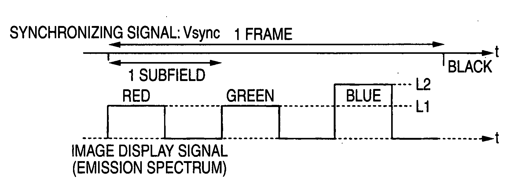
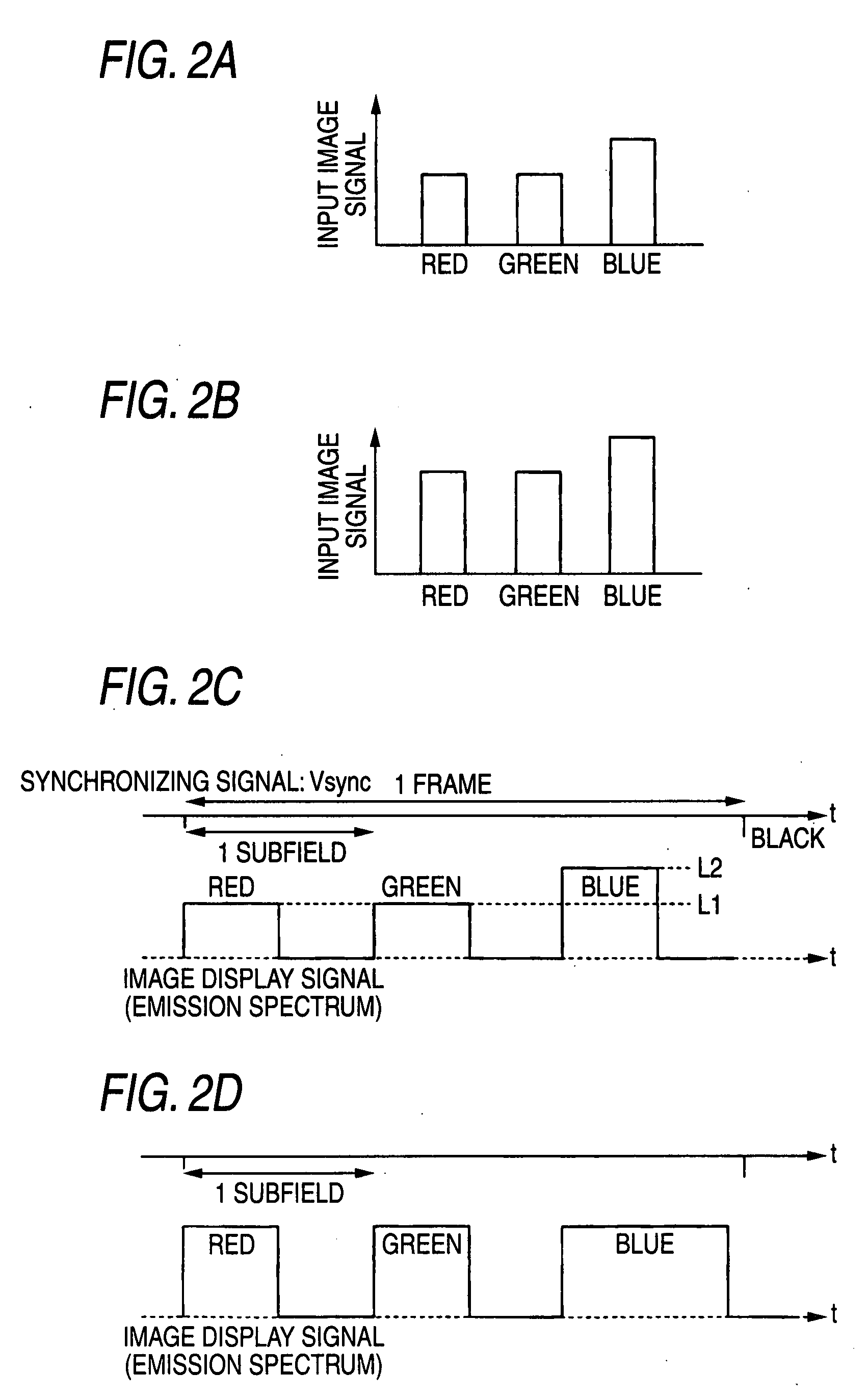
[0194]The liquid crystal display thus fabricated was disposed on a field sequential backlight constituted by four colors of LED light sources, a white display voltage of 2 V was applied to the liquid crystal cell, and color coordinates in the normal direction of the panel...

example 2

[0196]The lighting of the W light sources in the final subfield was not effected at the time of black display in Example 1 (variable gradation). The reproducible range of color at this time was the same, but the contrast ratio was 200:1.

example 3

[0197]The arrangement adopted was such that the LEDs of the B light sources were lit up in the final subfield in Example 1. When white and black display was effected, the light sources of the three colors of R, G, and B were lit up. When blue display was effected, the blue LEDs were lit up in the final subfield. The blue contrast ratio (blue CR) calculated from the ratio between the blue display luminance and the black display luminance improved from 700:1 to 1200:1.


PUM


Abstract

A liquid crystal display is provided and includes: a liquid crystal panel; light sources for illuminate light from M kinds of colors onto the liquid crystal panel; and a light source driving unit in which a one-frame period of an input image signal is divided into M or more subfields, and the light sources are sequentially driven in a time-sharing mode in correspondence with the subfields. The light source driving unit changes in correspondence with the input image signal at least one of an emission intensity and an emission period of a light source in a period of the subfield and the number of emission times of the light source during the one-frame period. Alternatively, a liquid crystal driving unit performs gradation control for changing a gradation characteristic independently with respect to each of the light sources, the gradation characteristic representing a relationship of emission intensity of each of the light sources with respect to the input image signal. The maximum luminance of a specific color in the subfield is thereby changed.

Description

BACKGROUND OF THE INVENTION[0001]1. Field of the Invention[0002]The present invention relates to a liquid crystal display, and more particularly to a technique for improving color reproducibility and dynamic contrast.[0003]2. Description of Related Art[0004]Cathode ray tubes (CRTs) have hitherto been mainly used as displays employed in office automation (OA) equipment such as word processors, laptop computers, and monitors for personal computers, portable terminals, televisions, and the like. In recent years, however, liquid crystal displays have come to be used widely instead of the CRTs.[0005]The displays using liquid crystal display devices (also called liquid crystal display panels) are capable of displaying images without providing a space (vacuum housing) for the two-dimensional scanning of an electron beam on the rear side of a display screen as in the cathode ray tube (CRT). Accordingly, these displays have characteristics of being thinner, more lightweight, and lower in pow...

Claims


Application Information

Patent Timeline
IPC IPC(8): G09G3/36
CPCG09G3/207G09G3/3413G09G3/3651G09G2300/0452G09G2300/0491G09G2360/16G09G2320/0242G09G2320/062G09G2320/066G09G2320/0666G09G2310/0235
Inventor HIRAKATA, JUNICHI
Owner FUJIFILM CORP
Why Eureka
Try Eureka