Rotational PZT micro-actuator, head gimbal assembly, and disk drive unit with same

a micro-actuator and rotating technology, applied in the direction of magnetic recording, data recording, instruments, etc., can solve the problems of limiting the servo bandwidth and capacity improvement of hdd, affecting the dynamic performance of hga, and limited the bandwidth of vcm, so as to achieve good resonance performance and position adjustment performance

Inactive Publication Date: 2007-09-27
SAE MAGNETICS (HK) LTD
View PDF27 Cites 51 Cited by
  • Summary
  • Abstract
  • Description
  • Claims
  • Application Information

AI Technical Summary

Benefits of technology

[0010] A main aspect of the present invention is to provide a HGA which can attain a good resonance performance and position adjusting performance.
[0011] Another aspect of the present invention is to provide a micro-actuator having a simple structure and a good position adjusting performance.
[0018] Compared with the prior art, the micro-actuator of the present invention uses two simple PZT elements that move in opposite directions when subjected to a predetermined voltage to adjust the position of the slider so that the manufacturing cost is low and the manufacturing process is simplified. In addition, the two side arms of the invention rotate in opposite directions. Thus, the slider undergoes a pure rotation. By keeping the slider's center of gravity stationary, less power is required for micro-actuation because the read / write transducer is located at the distal end of the slider. Thus, a larger head position adjustment capacity can be attained without increasing the power of micro-actuation. Furthermore, the micro-actuator of the present invention imparts only a small moment, and no inertia force on the suspension. The suspension resonance due to the micro-actuation is reduced. Desirably, the servo bandwidth is improved and the HDD storage capacity is increased.

Problems solved by technology

However, because of its large inertia the VCM has limited bandwidth.
This will affect the dynamic performance of the HGA and limit the servo bandwidth and the capacity improvement of HDD.

Method used


Image

  • Rotational PZT micro-actuator, head gimbal assembly, and disk drive unit with same
  • Rotational PZT micro-actuator, head gimbal assembly, and disk drive unit with same
  • Rotational PZT micro-actuator, head gimbal assembly, and disk drive unit with same

Examples


Embodiment Construction

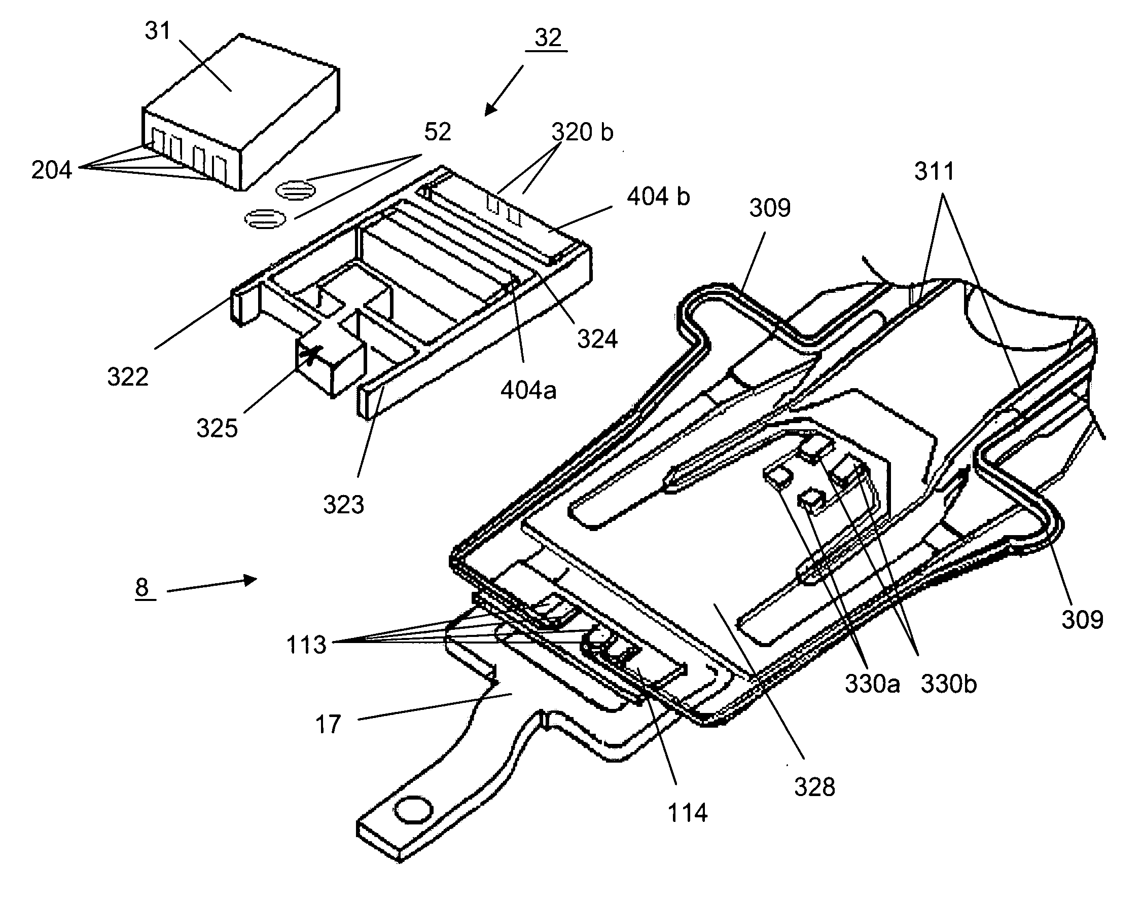
[0045] Referring to FIG. 3, a head gimbal assembly (HGA) 3 of the present invention comprises a slider 31, a micro-actuator 32 and a suspension 8 to load the slider 31 and the micro-actuator 32.

[0046] Also referring to FIG. 3, the suspension 8 comprises a load beam 17, a flexure 13, a hinge 15 and a base plate 11. On the flexure 13 a plurality of connection pads 308 are provided to connect with a control system (not shown) at one end and a plurality of electrical multi-traces 309, 311 are provided in the other end. Referring to FIGS. 4a, 4b and 5, the flexure 13 also comprises a suspension tongue 328 which is used to support the micro-actuator 32 and the slider 31. Referring to FIG. 6, the load beam 17 has a dimple 329 formed thereon to support the suspension tongue 328.

[0047] Referring to FIGS. 4b and 5, a limiter 207 is formed on the load beam 17 which extends through the suspension tongue 328 for preventing the suspension tongue 328 from being bent overly during normal operatio...


PUM

PropertyMeasurementUnit
voltageaaaaaaaaaa
gravityaaaaaaaaaa
flexibleaaaaaaaaaa

Abstract

A HGA of the invention includes a slider; a micro-actuator to adjust the position of the slider; and a suspension to support the slider and the micro-actuator. The micro-actuator includes two side arms; a load plate for supporting the slider, which is connected with at least one of the side arms; a pair of piezoelectric (PZT) elements connected with the side arms; and a support shaft coupled with the suspension, the support shaft being connected with the side arms and positioned between the PZT elements. The invention also discloses a disk drive unit using such a HGA.

Description

FIELD OF THE INVENTION [0001] The present invention relates to disk drive units, and particularly relates to a rotation-type micro-actuator and a head gimbal assembly with such micro-actuator. BACKGROUND OF THE INVENTION [0002] Disk drives are information storage devices that use magnetic media to store data. Referring to FIG. 1a, a typical disk drive in related art has a magnetic disk and a drive arm to drive a head gimbal assembly 277 (HGA). The HGA 277 has a suspension (213) with a slider 203 mounted thereon. The disk is mounted on a spindle motor which causes the disk to spin. The drive arm is provided with a voice-coil motor (VCM) for controlling the slider 203 to move from track to track across the surface of the disk to read data from or write data to the disk. [0003] However, because of its large inertia the VCM has limited bandwidth. Thus the slider 203 can not attain a quick and fine position control which will affect the ability of the slider 203 to read data from and wri...

Claims


Application Information

Patent Timeline
Patent Type & Authority Applications(United States)
IPC IPC(8): G11B21/24
CPCG11B5/4826G11B5/5556G11B5/4853G11B5/483
Inventor YAO, MINGGAOSHIRAISHI, MASASHI
Owner SAE MAGNETICS (HK) LTD
Why Eureka
Try Eureka