Light guide plate and backlight module using the same

a technology of light guide plate and backlight module, which is applied in the direction of instruments, lighting and heating apparatuses, optical elements, etc., can solve the problems of unavoidable formation of interference lines, such as a plurality of dark or brightness lines, on the light output surfa

Inactive Publication Date: 2007-09-27
HON HAI PRECISION IND CO LTD
View PDF6 Cites 65 Cited by
  • Summary
  • Abstract
  • Description
  • Claims
  • Application Information

AI Technical Summary

Benefits of technology

[0006]A light guide plate according to a preferred embodiment includes a light input surface and a light output surface adjoining the light input surface. The light output surface defines a first portion adjacent to the light input surface, a second portion connected with the first portion at a distance from the light input surface, and an imaginary boundary line between the first portion and the second portion. The light guide plate further includes a plurality of prism lenses arranged on the second portion of the light output surface, each prism lens extending along a direction perpendicular to the light input surface. The light guide plate further includes a plurality of elongated tetrahedral lenses arranged on the first portion of the light output surface, each tetrahedral lens having a side surface located at the imaginary boundary line perpendicularly to the light output surface. A relative height of each tetrahedral lens progressively increases with increasing distance from the light input surface.

Problems solved by technology

However, interference lines, such as a plurality of dark or brightness lines, are generally unavoidably formed on the light output surface adjacent the light input surface because the V-shaped prism lenses are aligned on the light output surface regularly and periodically, and especially since each longitudinal side of each V-shaped prism lens extends along a same direction.

Method used


Image

  • Light guide plate and backlight module using the same
  • Light guide plate and backlight module using the same
  • Light guide plate and backlight module using the same

Examples


Embodiment Construction

[0021]Reference will now be made to the drawings to describe preferred embodiments of the present light guide plate and backlight module using the same, in detail.

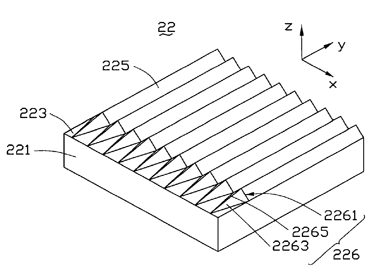
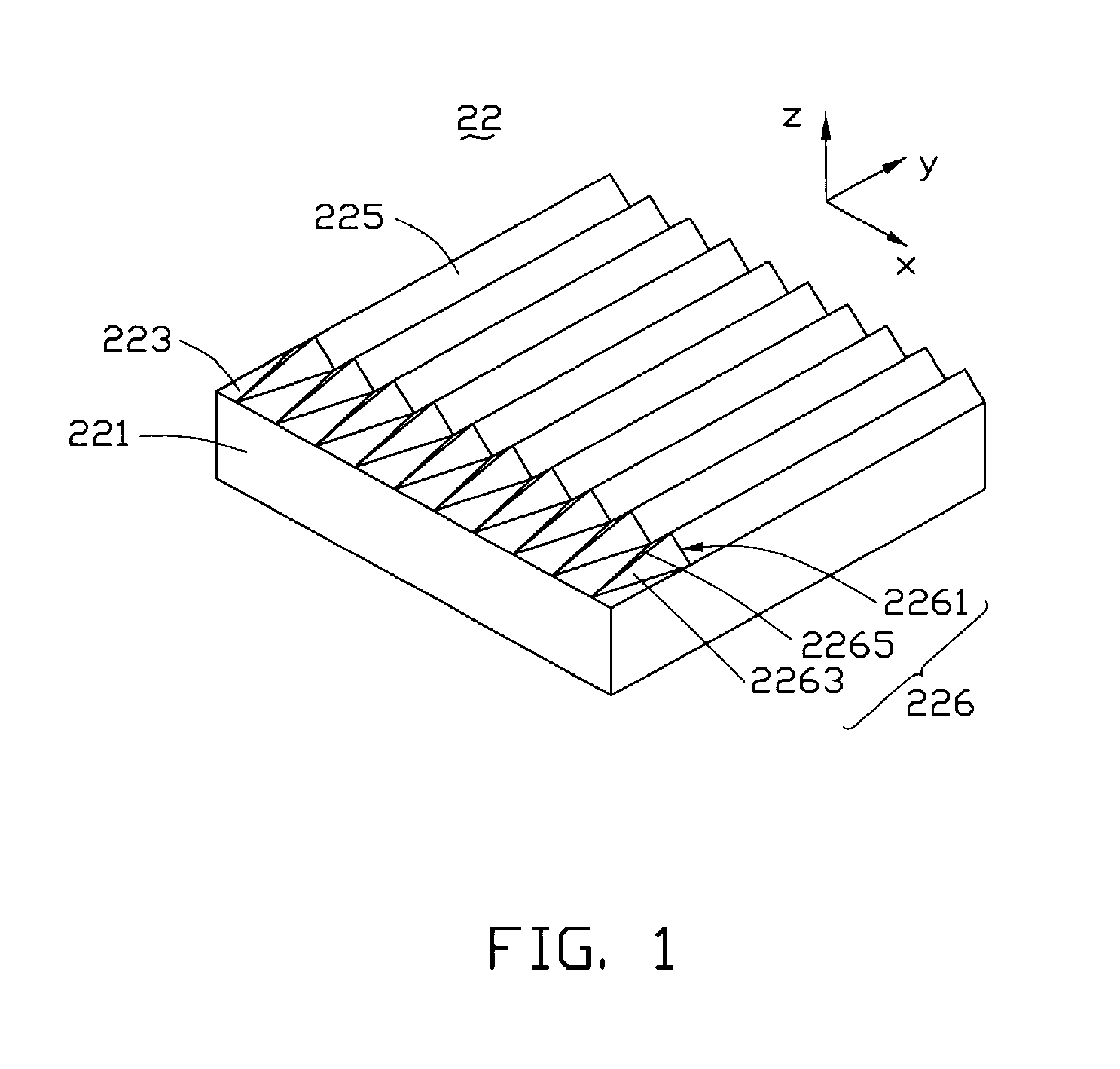
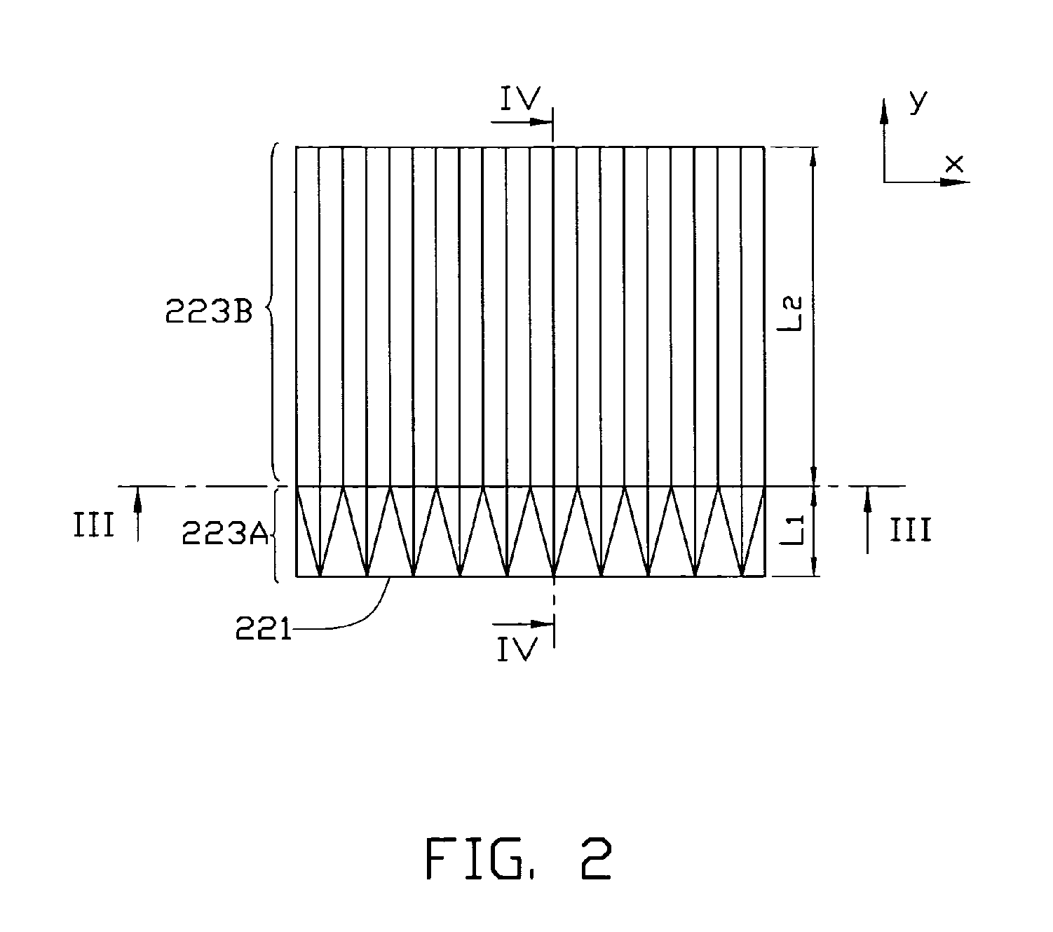
[0022]Referring to FIGS. 1 and 2, a light guide plate 22 in accordance with a first preferred embodiment is shown. The light guide plate 22 is a rectangular sheet, or alternatively may be generally cuneiform. In the illustrated embodiment, the light guide plate 22 is a rectangular sheet. The light guide plate 22 includes a light input surface 221 and a light output surface 223 adjoining the light input surface 221. The light output surface 223 defines a first portion 223A adjacent to the light input surface 221, a second portion 223B connected with the first portion 223A at a distance from the light input surface 221, and an imaginary boundary line III-III between the first portion 223A and the second portion 223B parallel to the light input surface 221. The light guide plate 22 further includes a plurality of elongated pr...


PUM


Abstract

A light guide plate includes a light input surface and a light output surface adjoining the light input surface. The light output surface defines a first portion adjacent to the light input surface, a second portion connected with the first portion away from the light input surface. The light guide plate further includes a plurality of prism lenses arranged on the second portion, each prism lens extending along a direction perpendicular to the light input surface, and a plurality of tetrahedral lenses arranged on the first portion of the light output surface, each tetrahedral lens having a side surface located at an imaginary boundary line perpendicularly to the light output surface. A relative height of each tetrahedral lens progressively increases with increasing distance from the light input surface. The present light guide plate and a backlight module using the same can efficiently decrease interference.

Description

FIELD OF THE INVENTION[0001]The present invention relates to light guide plates and backlight modules, particularly, to an edge-lighting type light guide plate and backlight module for use in, for example, a liquid crystal display (LCD).DISCUSSION OF THE RELATED ART[0002]In a liquid crystal display device, a liquid crystal is a substance that does not itself radiate light. Instead, the liquid crystal relies on light received from a light source, thereby displaying images and data. In the case of a typical liquid crystal display device, a backlight module powered by electricity supplies the needed light.[0003]Generally, backlight modules can be classified into an edge lighting type or a bottom lighting type based upon the location of lamps within the device. A typical edge lighting type backlight module has a light source arranged at a side portion of a light guiding plate for guiding light. The light source can be selected from one of a light emitting diode and a cold cathode fluore...

Claims


Application Information

Patent Timeline
Patent Type & Authority Applications(United States)
IPC IPC(8): F21V7/04
CPCG02B6/0038G02B6/0071G02B6/0061
Inventor LIAO, MING-YI
Owner HON HAI PRECISION IND CO LTD
Why Eureka
Try Eureka