Transferring system

a technology of transferring system and workpiece, which is applied in the direction of conveyor parts, electric devices, cranes, etc., can solve the problems of complicated configuration and control, damage to workpieces, and prone failure of loading/unloading thereof, so as to facilitate loading and/or unloading workpieces.

Inactive Publication Date: 2007-09-27
SAMSUNG ELECTRONICS CO LTD
View PDF15 Cites 17 Cited by
  • Summary
  • Abstract
  • Description
  • Claims
  • Application Information

AI Technical Summary

Benefits of technology

[0010]The present general inventive concept provides a transferring system to stably support a hoist unit or a workpiece in transferring the same between a transferring position and a storing position, to thereby rapidly load and / or unload the workpiece.

Problems solved by technology

However, in the conventional overhead transferring vehicle system, the workpiece may be damaged by a shock in movement between the transferring vehicle and the warehouse or the buffer.
Also, when a direction of the workpiece deviates, loading / unloading thereof is apt to fail.
Also, because the roller conveyer of the transferring vehicle moves between the moving loading position and the withdrawal position, the configuration and the control thereof are complicated, and a transferring time increases.

Method used


Image

  • Transferring system
  • Transferring system
  • Transferring system

Examples


Embodiment Construction

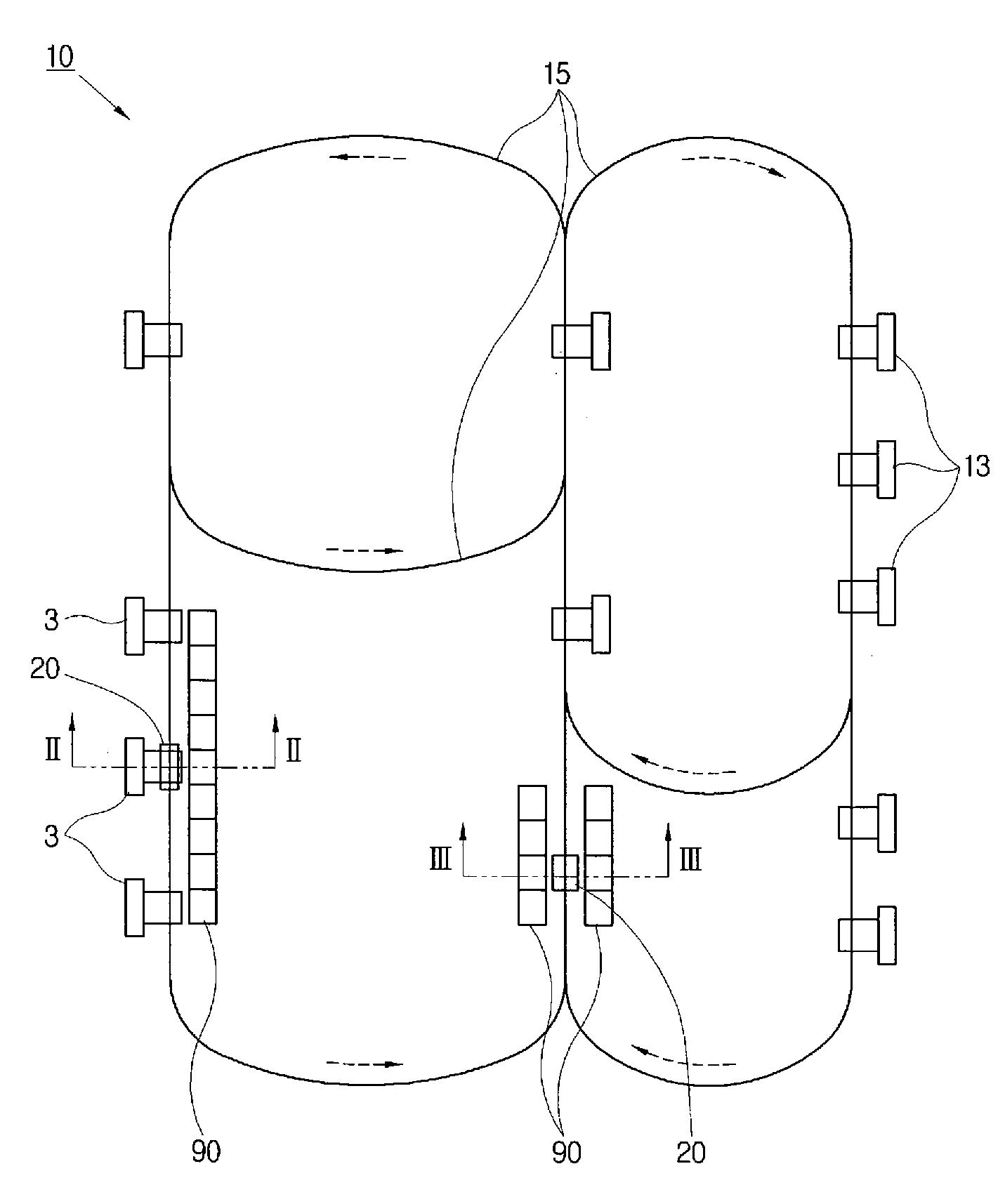
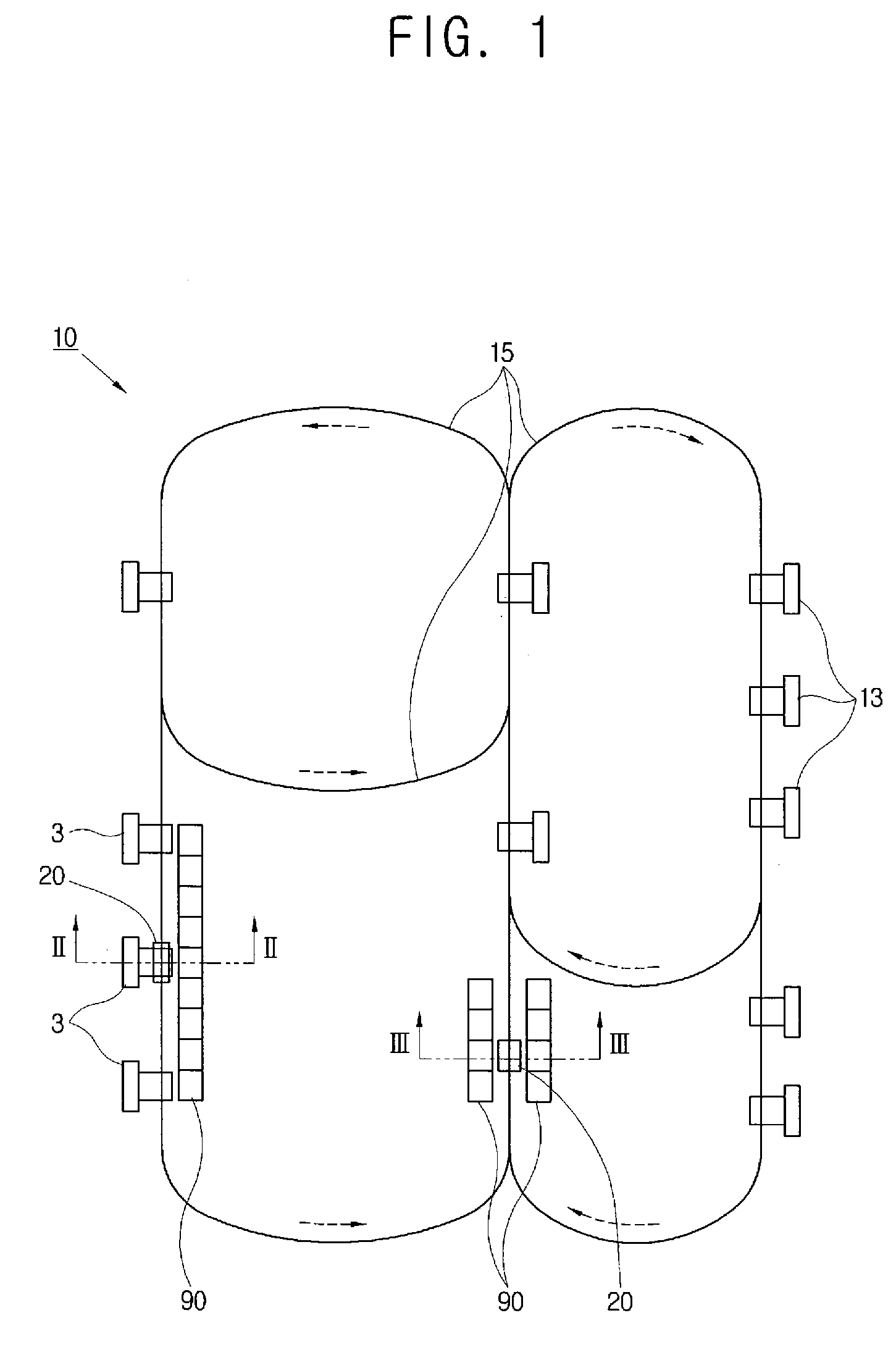
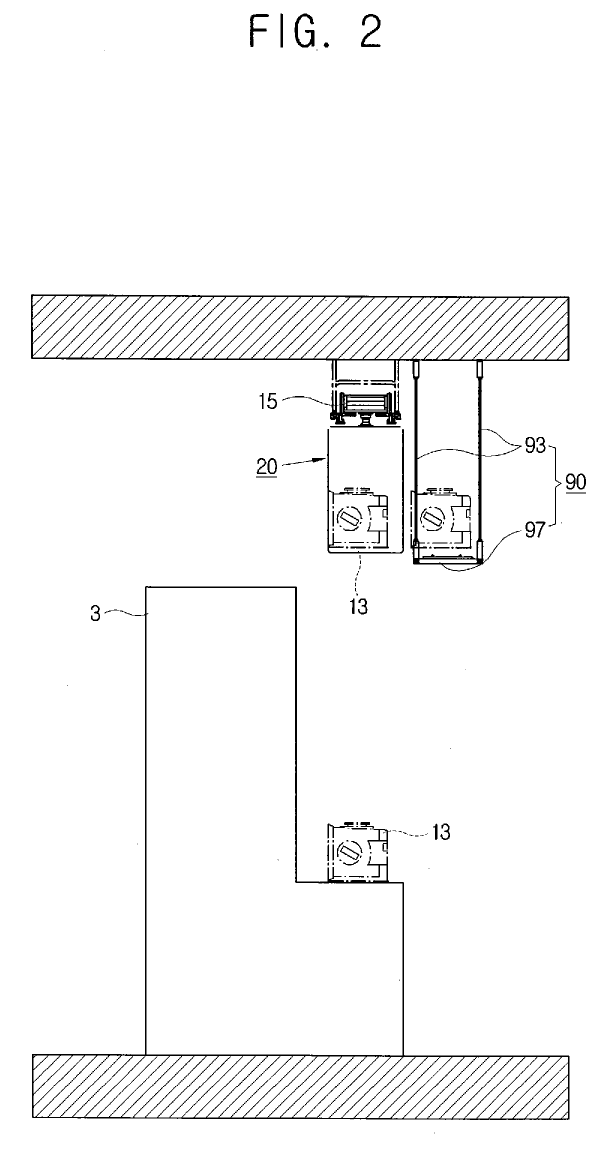
[0034]Reference will now be made in detail to the embodiments of the present general inventive concept, examples of which are illustrated in the accompanying drawings, wherein like reference numerals refer to the like elements throughout. The embodiments are described below in order to explain the present general inventive concept by referring to the figures. Hereinafter, among various transferring apparatuses, an overhead type transferring apparatus to transfer a reticle, FOUP, etc., which is used in a semiconductor process will be exemplarily described.

[0035]As illustrated in FIGS. 1 to 4, a transferring system 10 according to an embodiment of the present general inventive concept includes a rail 15 supported by or disposed on an installation surface such as a ceiling, a transferring apparatus 20 provided with a main body unit 21 to travel along the rail 15, a sliding unit 30 coupled to the main body unit 21 to relatively move between a transferring position and a storing position...


PUM


Abstract

A transferring system to travel along a rail to transfer and load and / or unload a workpiece include a transferring apparatus provided with a main body unit to travel along the rail, a sliding unit coupled to the main body unit to relatively move between a transferring position and a storing position with respect to the main body unit, and a hoist unit coupled to the sliding unit to move upward and downward the workpiece, and one or more buffering apparatus disposed beside a traveling path of the transferring apparatus to support the workpiece in the storing position, and provided with a supporting part to support the sliding unit when the sliding unit moves between the transferring position and the storing position.

Description

CROSS-REFERENCE TO RELATED APPLICATIONS[0001]This application claims priority under 35 U.S.C. §119(a) from Korean Patent Application No.2006-0026290, filed on Mar. 22, 2006, in the Korean Intellectual Property Office, the disclosure of which is incorporated herein by reference in its entirety.BACKGROUND OF THE INVENTION[0002]1. Field of the Invention[0003]The present general inventive concept relates to a transferring system, and more particularly, to a transferring system to stably support a hoist unit or a workpiece in transferring the same between a transferring position and a storing position.[0004]2. Description of the Related Art[0005]Generally, a transferring system includes a transferring apparatus traveling along a path such as a rail to transfer a workpiece, a processing station provided on the path to process the workpiece, and a buffering apparatus disposed beside the path to temporarily store the workpiece.[0006]The transferring apparatus may be classified into an autom...

Claims


Application Information

Patent Timeline
Patent Type & Authority Applications(United States)
IPC IPC(8): B65G47/90
CPCH01L21/67706H01L21/67769H01L21/67736H01L21/67733H01L21/68B66C21/00
Inventor CHANG, MIN-GU
Owner SAMSUNG ELECTRONICS CO LTD
Why Eureka
Try Eureka