Turbine blade and diaphragm construction

Inactive Publication Date: 2007-09-27
ALSTOM TECH LTD
View PDF11 Cites 11 Cited by
  • Summary
  • Abstract
  • Description
  • Claims
  • Application Information

AI Technical Summary

Benefits of technology

[0021]For easy fitting of the blades into the diaphragm during assembly, the side edges of each platform portion are substantially parallel to each other and to the chord line of the aerofoil portion. The relevant chord line may be the mean chord line of the aerofoil portion but is preferably the chord line of the aerofoil portion where it meets the relevant platform portion.
[0022]To minimise the amount

Problems solved by technology

This form of construction has performance advantages compared to the spacer band type, but has much higher manufact

Method used


Image

  • Turbine blade and diaphragm construction
  • Turbine blade and diaphragm construction
  • Turbine blade and diaphragm construction

Examples


Example

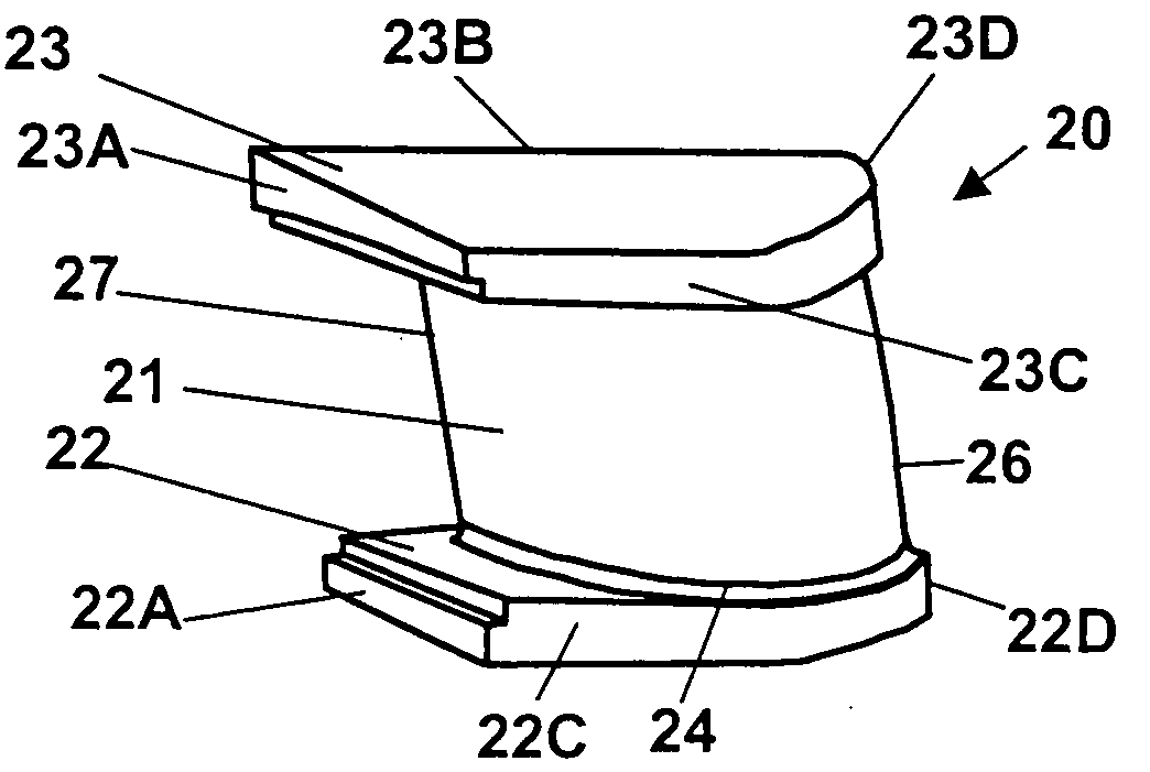
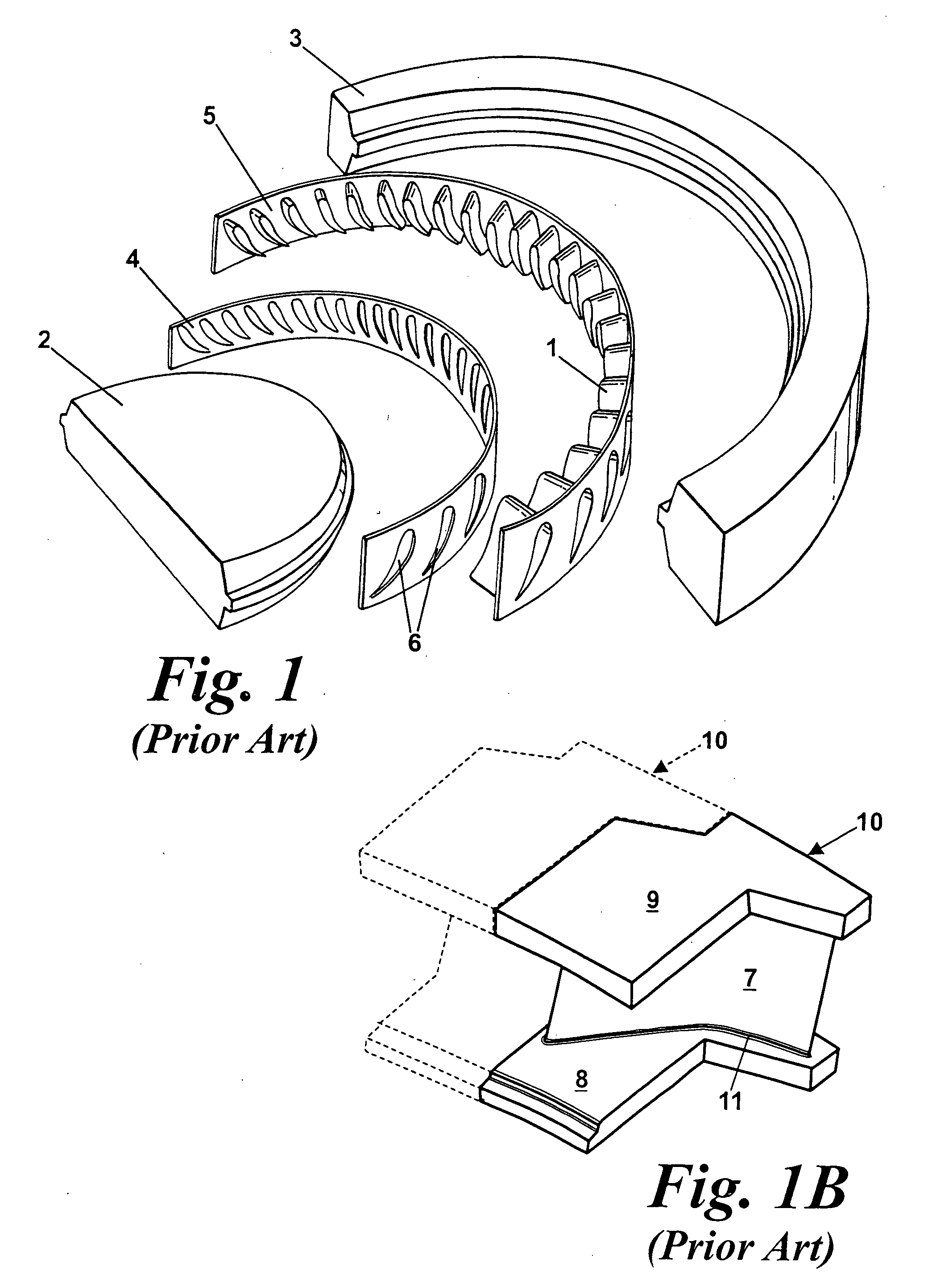
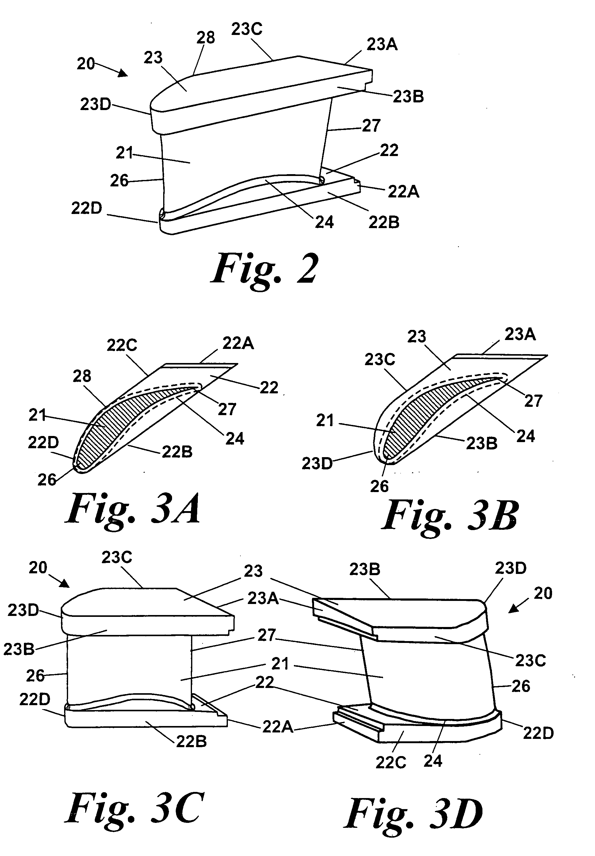
[0050]FIG. 2 shows a static blade 20 for use in a diaphragm construction according to the present invention. It has an aerofoil portion 21 similar to aerofoil 7 of static blade 10 in FIG. 1B. However, although it has integral inner and outer platform portions 22, 23, respectively, they are much smaller than the corresponding platform portions 8, 9 of blade 10. In fact, the opposed side edges 22A, 22B and 23A, 23B of platform portions 22, 23 run substantially parallel to each other and to the chord line of the aerofoil portion and, at least for the inner platform 22, the distance between the side edges is only just sufficient to embrace the cross-section of the aerofoil portion together with its corner fillets 24.

[0051]Turning to FIG. 3, FIGS. 3A and 3B are plan views of the platform portions. FIG. 3A is a view looking radially inwards on the radially inner platform portion 22, with the cross-section of the aerofoil 21 shown as the hatched area and the extent of the aerofoil corner f...


PUM

PropertyMeasurementUnit
Electric chargeaaaaaaaaaa
Digital informationaaaaaaaaaa

Abstract

An axial flow turbine blade and diaphragm construction comprises an annulus of static turbine blades 20 and inner and outer spacer rings 40, 42 having apertures 41, 43 shaped to accommodate inner and outer platform portions 22, 23 of the blades, whereby the platform portions and the spacer rings together form inner and outer port walls of the turbine diaphragm. A particular feature of the blades is that the inner and outer platform portions 22 and 23 have straight side edges 22B, 22C and 23B, 23C, which are joined to each other by curved leading edges 22D and 23D that in plan view have a shape that follows the edge of the corner fillet 24 in the region of the leading edge 26 of the aerofoil 21.

Description

FIELD OF THE INVENTION[0001]The present invention relates to a novel construction for a ring of static blades for use in an axial flow turbine. It is particularly, but not exclusively, relevant to steam turbine diaphragms.BACKGROUND OF THE INVENTION[0002]The present invention is related to two known types of construction called “spacer band” and “platform”. In the spacer band type of construction, shown in FIG. 1A, the blade aerofoils 1 are fixed to radially inner and outer structural members 2, 3 by means of inner and outer annular “bands”4, 5, which are rolled from flat strip. Holes 6 are cut in the bands 4, 5 (e.g., by laser) to match the cross-section of the aerofoil shape, the ends of the aerofoils then being inserted into the holes and fillet welded into place. The bands are in turn welded to the inner and outer members 2, 3 to form the steam passage wall, or so-called “port wall”.[0003]An advantage of spacer band construction is that it involves a relatively small amount of m...

Claims


Application Information

Patent Timeline
IPC IPC(8): F04D29/44
CPCB23P15/006F01D5/225F01D9/04F04D29/542Y10T29/49323F05D2240/10F05D2220/31F05D2250/70F05D2250/71F05D2240/80F04D29/544
Inventor BLATCHFORD, DAVID PAULNELMES, DAVID JOHNCOLTAR, BRYAN VINCENT
Owner ALSTOM TECH LTD
Why Eureka
Try Eureka