[0043]In preferred embodiments of each of the forms of the invention described in broad terms above, the transmitter may be a transmitter of a base station, the receiver may be a receiver of a user station (in other words, the invention may find particular use, and provide particular benefits in relation to, downlink transmissions), and the lattice reduction matrix may be calculated at the base station such that the decomposed representation of the lattice reduction matrix may be transmitted from the base station to the user station. One of the benefits provided by these preferred embodiments is that they enable transfer of the computationally
complex calculation of the lattice reduction matrix from the user station to the base station while incurring only moderate signalling overheads due to efficient signalling of the lattice reduction matrix, namely in a decomposed form, from the base station to the user station. This can therefore enable
performance improvement using, in particular, simple conventional receiver structures.
[0046]As explained above, the so-called
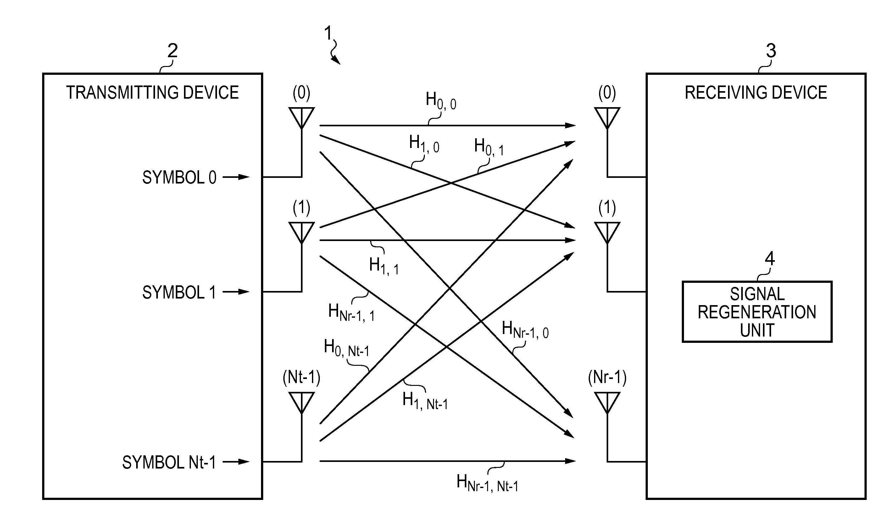
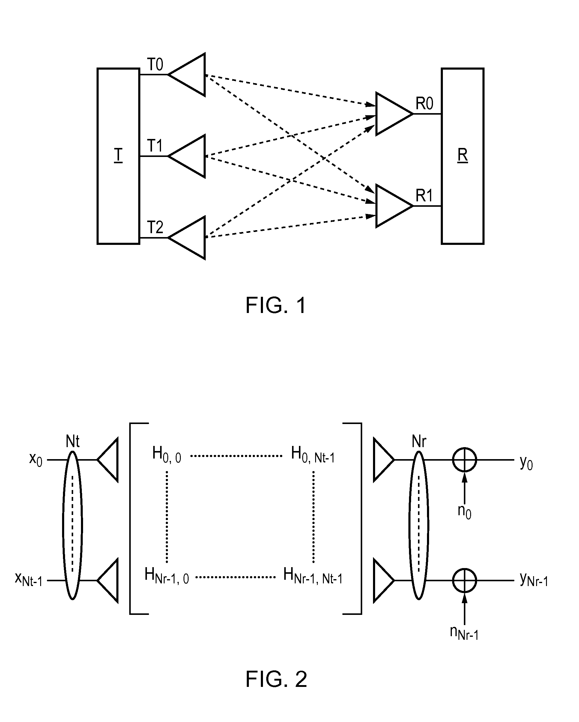
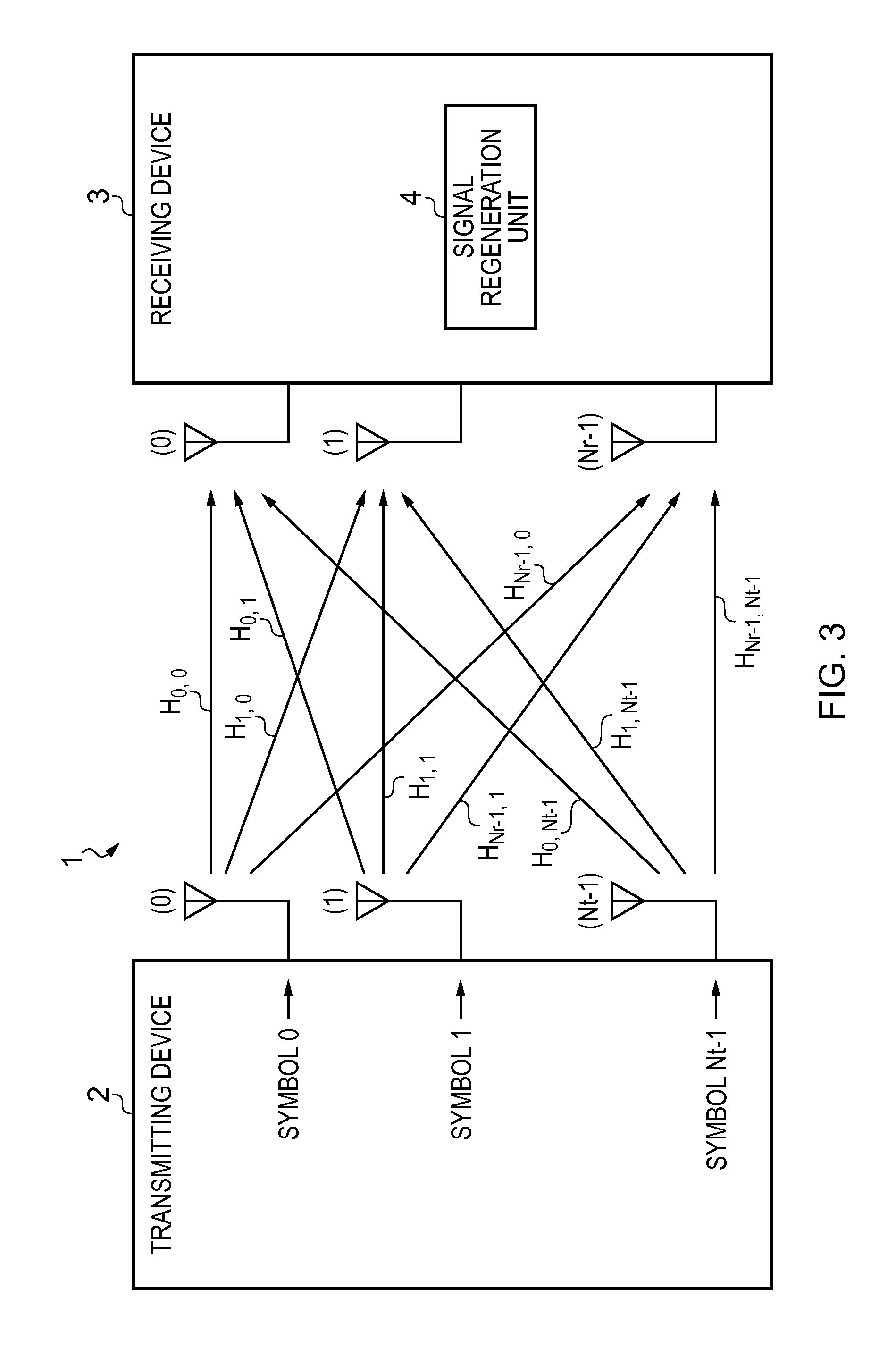
MIMO channel in MIMO wireless communication schemes can be mathematically represented by a matrix, namely the so-called channel matrix, and where there is correlation between the individual SISO channels which make up the
MIMO channel, this can be represented by rank deficiency of the channel matrix (i.e. by linear dependence between at least certain of the rows and columns of the channel matrix).
Lattice reduction is used in the various embodiments of the present invention in order to obtain, at the receiver, an improved estimate of the transmitted signal based on the received signal (i.e. an estimate of the signal transmitted by the transmitter based on the signal received by the receiver).
Lattice reduction helps to minimise detrimental effects (e.g. on receiver performance etc) caused by correlation in the
MIMO channel.
[0047]In the preferred embodiments discussed above, the transmitter is a transmitter of a base station, the receiver is a receiver of a user station, and the lattice reduction matrix is calculated at the base station so that the computationally
complex calculation of the lattice reduction matrix is transferred to the base station (which typically has greater computational resources than the user station). It has also been explained that, in the present invention (or at least most embodiments thereof), a decomposed representation of the lattice reduction matrix is transmitted from the base station to the user station. In other words, rather than transmitting the lattice reduction matrix itself (or the individual entries thereof), a decomposed form of the lattice reduction matrix is transmitted, and this enables the invention to achieve significant savings in terms of signalling overheads.
[0049]In embodiments where the lattice reduction matrix and the decomposed representation thereof meet the description given in the previous
paragraph, a set of totally unimodular matrices may be provided. In arriving at the lattice reduction
matrix decomposition (i.e. the decomposed representation of the lattice reduction matrix), one or more of the totally unimodular matrices from the set may be chosen such that the product of the chosen totally unimodular matrices equals the lattice reduction matrix. Those skilled in the art will recognise that, at least in some instances, there may be multiple different product combinations of totally unimodular matrices from the set which equal the lattice reduction matrix. In other words, there may be more than one different combination of totally unimodular matrices in the set which, when multiplied together, equal the lattice reduction matrix. It is possible that any such combination may be used as the decomposed representation of the lattice reduction matrix for the purposes of the invention. However, it may be preferable to choose combinations involving the least number of totally unimodular matrices, or the least number of different totally unimodular matrices (see powers discussed below), so as to minimise the amount of information to be transmitted (i.e. minimise the signalling overhead associated with transmitting the lattice reduction
matrix decomposition).
[0050]An identifying index may be assigned to each of the totally unimodular matrices in the above-mentioned set. Therefore, in transmitting the decomposed representation of the lattice reduction matrix from the base station to the user station, rather than transmitting the chosen totally unimodular matrices from the set whose product equals the lattice reduction matrix (i.e. rather than transmitting the totally unimodular matrices themselves or the individual elements thereof), only the identifying index for each of those chosen totally unimodular matrix is transmitted. In this way, a significant saving may be achieved in terms of the signalling overhead associated with transmitting the lattice reduction
matrix decomposition.
[0051]Those skilled in the art will recognise that, in many instances, a particular totally unimodular matrix may appear in the lattice reduction matrix
decomposition more than once. In other words, in the combination of totally unimodular matrices which equals the lattice reduction matrix when multiplied together, a particular totally unimodular matrix may be multiplied by itself one or more times. In fact, there may be more than one totally unimodular matrix, each multiplied by itself one or more times. In these situations, rather than transmitting the index for each such totally unimodular matrix the required number of times, a power m may be transmitted for each such totally unimodular matrix (where m−1 is the number of times that totally unimodular matrix is multiplied by itself). Therefore, as an example, if a particular totally unimodular matrix D were multiplied by itself three times (i.e. D×D×D×D=D4), instead of transmitting the identifying index for matrix D four times as part of the transmitted lattice reduction matrix
decomposition, the same information may be transmitted by transmitting the identifying index for matrix D once along with the power four (i.e. m=4). In this way, the number of bits required to be transmitted in order to represent totally unimodular matrices multiplied by themselves one or more times in the lattice reduction matrix
decomposition may be reduced.


