Devices and methods for annular repair of intervertebral discs

a technology of annular repair and disc, which is applied in the field of devices and methods for the repair of annular disc, to achieve the effects of preventing the ingress of nerves, facilitating healing, and reducing back pain

Inactive Publication Date: 2007-09-27
ANULEX TECH
View PDF1 Cites 97 Cited by
  • Summary
  • Abstract
  • Description
  • Claims
  • Application Information

AI Technical Summary

Benefits of technology

[0021] As will become apparent from the following detailed description, the improved devices and methods of the present invention may reduce if not eliminate back pain while maintaining near normal anatomical motion. Specifically, the present invention provides disc reinforcement devices to reinforce a damaged disc, while permitting relative movement of the vertebrae adjacent the damaged disc. The devices of the present invention are particularly well suited for minimally invasive methods of implantation.
[0022] The reinforcement devices of the present invention may provide three distinct functions. Firstly, the reinforcement devices may mechanically stabilize and strengthen the disc to minimize if not eliminate chronic irritation of nerve roots and nerves around the periphery of the disc annulus. Secondly, the reinforcement devices may radially and / or circumferentially compress the disc to close fissures, fractures and tears, thereby preventing the ingress of nerves as well as potentially facilitating healing. Thirdly, the reinforcement devices may be used to stabilize the posterior disc after a discectomy procedure in order to reduce the need for re-operation.

Problems solved by technology

Secondly, the reinforcement devices may radially and / or circumferentially compress the disc to close fissures, fractures and tears, thereby preventing the ingress of nerves as well as potentially facilitating healing.

Method used


Image

  • Devices and methods for annular repair of intervertebral discs
  • Devices and methods for annular repair of intervertebral discs
  • Devices and methods for annular repair of intervertebral discs

Examples


Embodiment Construction

[0052] The following detailed description should be read with reference to the drawings in which similar elements in different drawings are numbered the same. The drawings, which are not necessarily to scale, depict illustrative embodiments and are not intended to limit the scope of the invention.

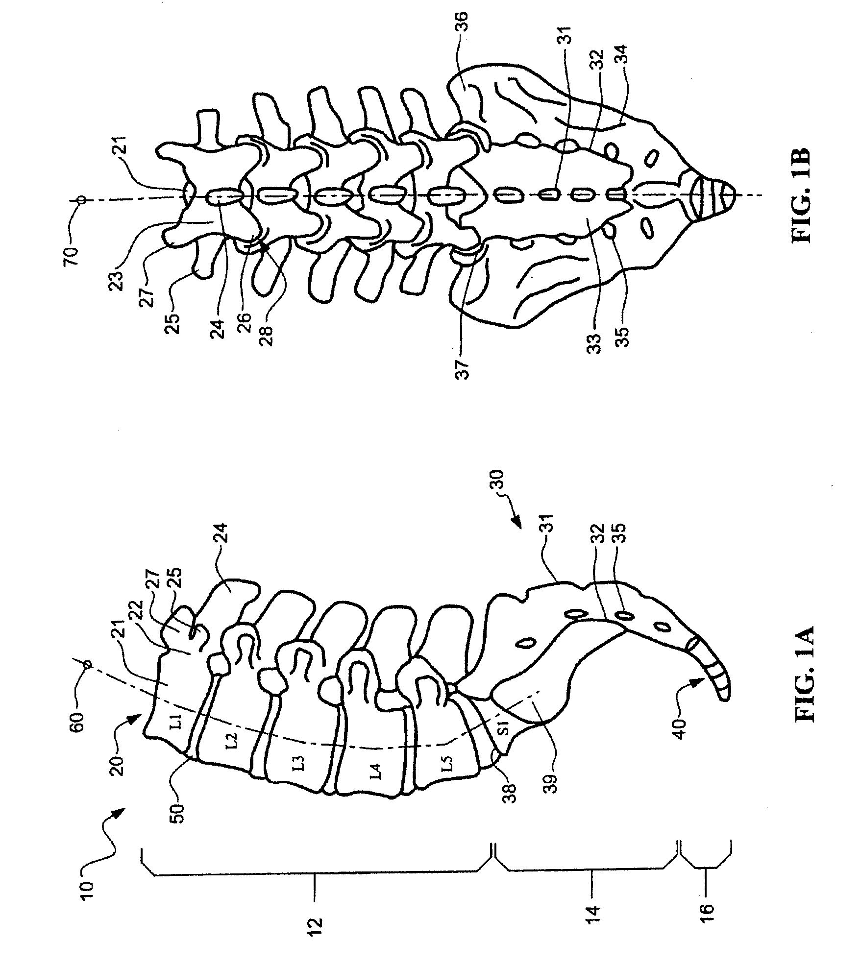
[0053] With reference to FIGS. 1A and 1B, the lower portion of an adult human vertebral column 10 is illustrated in left lateral and posterior views, respectively. The upper portion of the vertebral column 10 includes the thoracic region and the cervical region, which are not shown for purposes of simplified illustration only. The lower portion of the vertebral column 10 includes the lumbar region 12, the sacrum 14 and the coccyx 16. The sacrum 14 and the coccyx 16 are sometimes collectively referred to as the pelvic curvature.

[0054] The vertebral column 10 includes an axis of curvature 60 which generally forms a double-S shape when viewed laterally. The vertebral column 10 also includes ...


PUM

PropertyMeasurementUnit
temperaturesaaaaaaaaaa
temperatureaaaaaaaaaa
frequenciesaaaaaaaaaa

Abstract

Devices and methods for treating a damaged intervertebral disc to reduce or eliminate associated back pain. The present invention provides disc reinforcement therapy (DRT) which involves implanting one or more reinforcement members in and preferably around the annulus of the disc. The reinforcement members may be used to stabilize the annulus and / or compresses a portion of the annulus so as to reduce a bulge and / or close a fissure. The implantable devices and associated delivery tools may incorporate heating capabilities to thermally treat the annular tissue. Alternatively or in combination, other devices may be specifically employed for such thermal treatment.

Description

CROSS REFERENCE TO RELATED APPLICATIONS [0001] The present application is a continuation of U.S. application Ser. No. 10 / 943,525 filed Sep. 17, 2004; which is a continuation of U.S. application Ser. No. 10 / 390,970, filed Mar. 18, 2003, now U.S. Pat. No. 6,805,695; and is a continuation-in-part of 10 / 055,780, filed Jan. 22, 2002, now U.S. Pat. No. 6,689,125. U.S. application Ser. No. 10 / 390,970 is a continuation-in-part of 09 / 685,401, filed Oct. 10, 2000, now U.S. Pat. No. 6,579,291; which is a continuation-in-part of 10 / 093,990, filed Mar. 7, 2002, now U.S. Pat. No. 6,835,205; which is a continuation of 09 / 542,972, filed Apr. 4, 2002, now U.S. Pat. No. 6,402,750; and claims the benefit of U.S. Provisional Application No. 60 / 263,343, filed Jan. 22, 2001; and claims the benefit of U.S. Provisional Application No. 60 / 368,108 filed Mar. 26, 2002 entitled DEVICES AND METHODS FOR THE TREATMENT OF SPINAL DISORDERS, the entire disclosure of which is incorporated herein by reference.FIELD OF...

Claims


Application Information

Patent Timeline
Patent Type & Authority Applications(United States)
IPC IPC(8): A61F2/44A61B17/00A61B17/04A61B17/16A61B17/34A61B17/70A61B17/84A61B17/86A61B17/88A61B18/08A61B18/14A61B19/00
CPCA61B17/0401A61F2310/00976A61B17/3468A61B17/3472A61B17/842A61B17/86A61B17/8897A61B18/08A61B18/14A61B2017/00084A61B2017/00261A61B2017/00557A61B2017/0409A61B2019/307A61F2/442A61F2/4611A61F2002/30062A61F2002/30095A61F2002/30579A61F2002/30841A61F2002/4435A61F2002/4627A61F2210/0004A61F2210/0023A61F2310/00017A61F2310/00023A61B17/1671A61F2002/30092A61B2090/037
Inventor KEITH, PETER T.ATKINSON, ROBERT E.
Owner ANULEX TECH
Why Eureka
Try Eureka