Femoral and humeral stem geometry and implantation method for orthopedic joint reconstruction

a stem and humeral technology, applied in the field of orthopaedic implants, can solve the problems of instability of the shoulder joint, disruption of the soft tissue, and difficulty in so as to facilitate the insertion of the proximal body portion, facilitate the reaming of bone, and improve the conformance and fixation of the stem implan

Inactive Publication Date: 2007-09-27
TORNIER INC
View PDF143 Cites 79 Cited by
  • Summary
  • Abstract
  • Description
  • Claims
  • Application Information

AI Technical Summary

Benefits of technology

[0017] In accordance with another embodiment, the stem component can taper from the proximal body portion toward the distal body portion to define medial and lateral curved surfaces. The medial and lateral curved surfaces can be configured to mimic the geometric shape of the bone for improving conformance and fixation of the stem component to the central cavity region of the bone. In this regard, the proximal body of the stem component can be inserted into a central cavity region created in the bone of a joint. The attachment portion can be tapered. Further, the bone can be a humerus. The humerus can comprise a proximal portion having a shape and a distal portion. The medial and lateral curved surfaces can conforms to the shape of the proximal portion of the implant. Further, the distal section of the stem component can have a cylindrical, elliptical, tapered, or irregular shape. Additionally, the distal body portion of the stem component can further comprise at least one feature selected from the group consisting of: a groove, a slot, a cutout, and a protrusion.
[0022] Further, in a method of implanting an orthopedic reconstructive joint replacement stem implant is also provided in accordance with another embodiment. The method can comprise: resecting a head of a bone of a joint; using a single instrument to successively broach and ream a central cavity region in the bone of the joint; and inserting a proximal body portion of the stem implant into the central cavity region of the bone of the joint. In particular, embodiments disclosed herein can facilitate the insertion of the proximal body portion into the central cavity region of the bone of the joint can be performed without damaging the supraspinatus. The method can further comprise the step of resecting a neck of the bone of the joint. In this method, the bone can be, for example, a femur or a humerus. Also, the joint can be, for example, a hip joint or a shoulder joint.
[0023] Another embodiment of the method can further comprise the step of selecting a stem implant in response to a geometric shape of the central cavity region of the bone. As mentioned above with respect to an embodiment of the stem implant, the stem implant can taper from the proximal body portion toward a distal body portion to define medial and lateral curved surfaces. Thus, the method can be implemented such that the medial and lateral curved surfaces can be configured to mimic the geometric shape of the central cavity region of the bone for improving conformance and fixation of the stem implant to the central cavity region of the bone.
[0024] In yet another embodiment, an instrument is provided for creating a central cavity region in a bone of a joint. The instrument comprises a broaching section, a reaming section, and a handle. The reaming section can be disposed at a distal end of the instrument. The reaming section can be sized and configured to facilitate reaming of the bone. The broaching section can be disposed axially adjacent to the reaming section and can be sized and configured to facilitate broaching of the central cavity region of the bone successive to the reaming of the bone by the reaming section. The handle can be disposed at a proximal end of the instrument and being coupled to the broaching and reaming sections for facilitating driving of the broaching and reaming sections.

Problems solved by technology

The shoulder is an unstable joint easily subject to injury because of its range of motion, and because the ball of the humerus is larger than the glenoid that holds it.
Some shoulder problems arise from the disruption of these soft tissues due to injury or overuse, or underuse of the shoulder.
Other problems can arise from degenerative processes.
Anterior instability may occur when the arm is placed in a throwing position.
Both partial and complete dislocation cause pain and unsteadiness in the shoulder joint.
Osteoarthritis and rheumatoid arthritis can cause destruction of the shoulder joint and surrounding tissue and degeneration and tearing of the capsule or rotator cuff.
However, currently available treatment options are less than adequate in restoring shoulder joint function.
Existing devices have focused on modifying only the most proximal portion of the stem geometry, known as the neck, to adjust for different angles but do not accommodate variation of the proximal body shape.
Since the size, location, and orientation of the head with respect to the humeral canal vary greatly from person to person, a single stem geometry per size cannot accommodate natural head placement or proximal body shape.
This typically results in a proximal fit that is poor because rotating an eccentric head adjusts both posterior and medial head location at the same time, virtually excluding the possibility of perfect placement.
This excessively small proximal body causes poor proximal fixation and leads to over-reliance on distal fixation.
Over time, when too much emphasis is placed on distal fixation, the strength of the proximal bone begins to deteriorate.
This, in turn leads to stem loosening and potentially fracture.
While this may improve head center placement, it offers little to accommodate varying shapes of the proximal body.

Method used


Image

  • Femoral and humeral stem geometry and implantation method for orthopedic joint reconstruction
  • Femoral and humeral stem geometry and implantation method for orthopedic joint reconstruction
  • Femoral and humeral stem geometry and implantation method for orthopedic joint reconstruction

Examples


Embodiment Construction

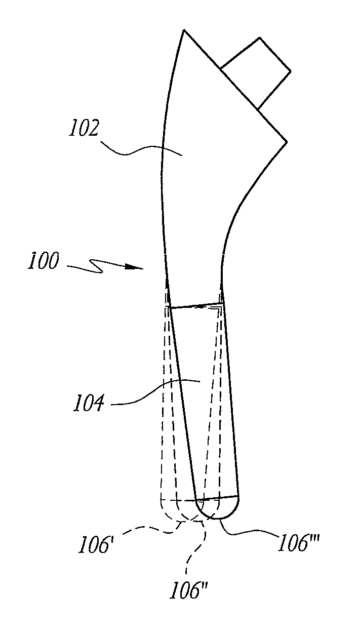
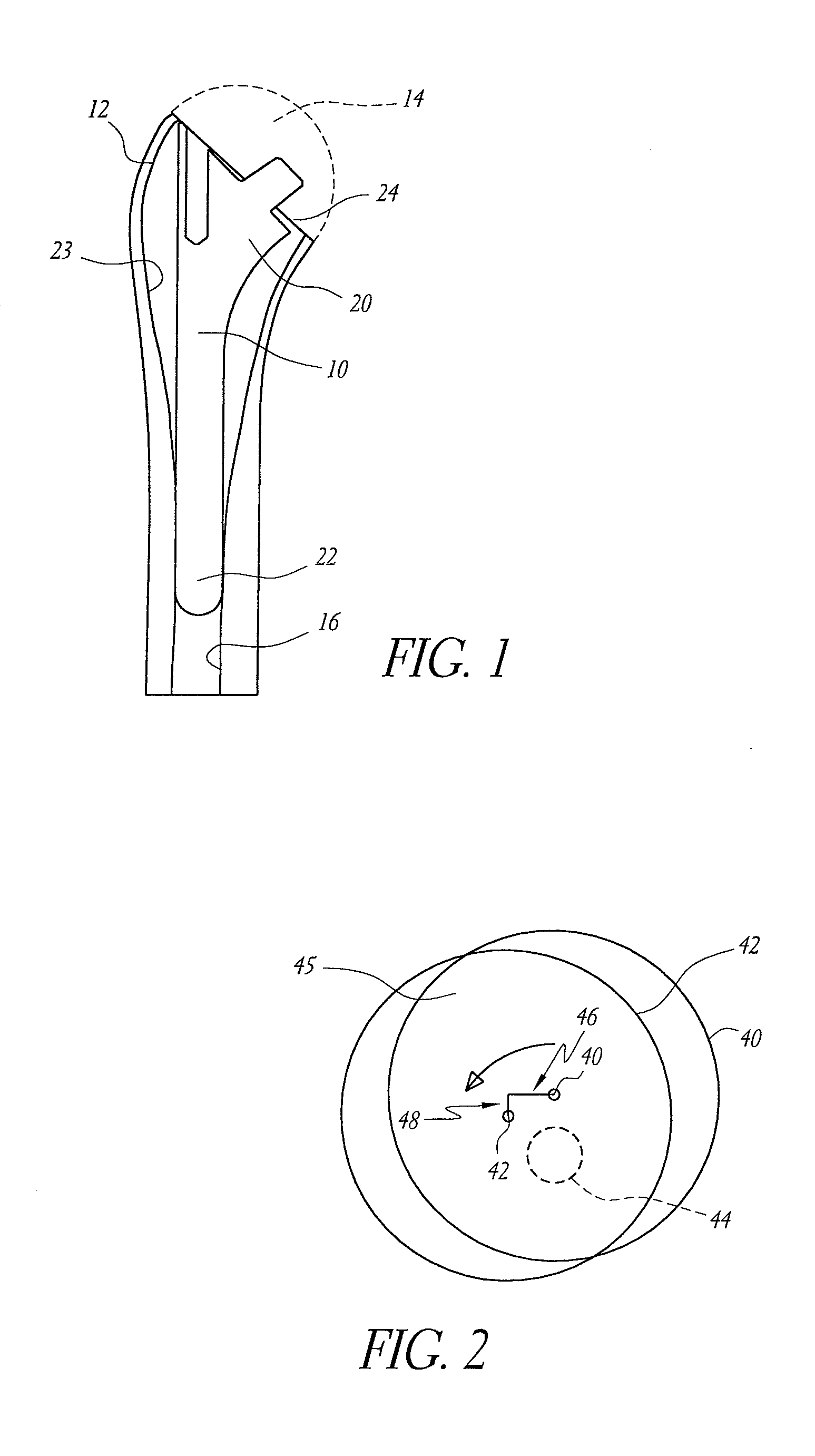
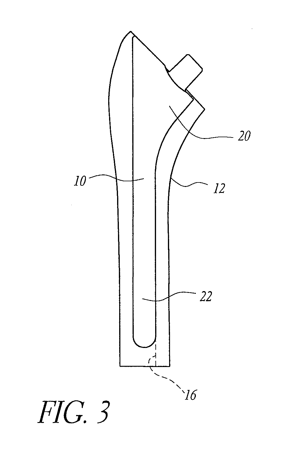
[0050] As used herein, the term “stem” is a broad term that is used to designate a device that is implanted into the bone for the purpose of supporting a functional component of a joint replacement and resisting the loads applied to the functional component. For example, a stem can be a device implanted into a humerus or femur to support a modular prosthetic humeral or femoral head (i.e. the supported structure). In other embodiments, the supported structure can be an integral part of the stem, as with a monolithic stem and head. Femoral and humeral stems typically include distal and proximal sections as well as a taper or other coupling device to which the functional component is attached. Additionally, femoral stems typically include a neck section that extends the distance between the proximal section and the head. The neck is not embedded in the bone, but sits proud. As used herein, the term “neck” can refer to the portion of a femoral stem that does not reside within the femur ...


PUM


Abstract

The present inventions relate to devices and methods that improve the positioning and fit of orthopedic reconstructive joint replacement stem implants relative to existing methods. For example, an embodiment of the device provides a stem component comprising proximal and distal body portions that can be configured to mimic a geometric shape of a central cavity region created in a bone of a joint for improving conformance and fixation of the stem component thereto. Further, another embodiment provides a system of stem implants that each have a unique medial offset for facilitating the matching of an implant to the geometry of a central cavity region of a bone. Additionally, an inclination angle of a resection surface of each of the implants in the system can remain constant or vary as a function of the medial offset.

Description

PRIORITY INFORMATION [0001] The present application claims the priority benefit under 35 U.S.C. § 119(e) to U.S. Provisional Application 60 / 784,236, filed Mar. 21, 2006, the entire contents of which are expressly incorporated by reference herein.BACKGROUND [0002] 1. Field of the Inventions [0003] The present inventions relates generally to orthopedic implants, and more specifically, to a reconstructive joint replacement implant and a method of positioning and fitting such an implant. [0004] 2. Description of the Related Art [0005] Anatomically, a joint is generally a movable junction between two or more bones. As used herein, the term “joint” is a broad term that is meant to include the different kinds of ligaments, tendons, cartilages, bursae, synovial membranes and bones comprising the mobile skeletal system of a subject in various quantities and configurations. [0006] For example, the hip joint is a ball and socket joint comprising the “ball” at the head of the thigh bone (femur)...

Claims


Application Information

Patent Timeline
Patent Type & Authority Applications(United States)
IPC IPC(8): A61F2/36A61B17/16A61F2/40
CPCA61B17/164A61F2250/0062A61B17/1668A61B17/1684A61B2017/0046A61B2017/00464A61B2019/462A61F2/36A61F2/40A61F2/4059A61F2002/30332A61F2002/30538A61F2002/3054A61F2002/30543A61F2002/30604A61F2002/30607A61F2002/30616A61F2002/3625A61F2002/3631A61F2002/4018A61F2002/4051A61F2002/4062A61F2002/4077A61F2220/0033A61F2250/0006A61B17/1659A61B2090/062A61F2/3662
Inventor REUBELT, LEO M.VERRILLO, PETER L.
Owner TORNIER INC
Why Eureka
Try Eureka