Data transfer control apparatus

a control apparatus and data technology, applied in the direction of electric digital data processing, instruments, climate sustainability, etc., can solve the problems of reducing efficiency and unexpectedly taking a lot of time for data transfer, and achieve efficient and fast data transfer, reduce the number of clock cycles, and reduce the effect of clock cycles

Inactive Publication Date: 2007-09-27
RENESAS ELECTRONICS CORP
View PDF9 Cites 2 Cited by
  • Summary
  • Abstract
  • Description
  • Claims
  • Application Information

AI Technical Summary

Benefits of technology

[0011] The invention has been made to solve the aforementioned problems and an object thereof is to provide a data transfer control apparatus which can execute data transfer efficiently and quickly in fewer clock cycles.
[0013] As mentioned above, according to the invention, as data transfer via an exclusive transfer bus is performed between the first bus slave and a selected one of a plurality of second bus slaves in accordance with an instruction from the bus master, data to be transferred does not go through the bus master. This reduces the number of clock cycles for transfer through the bus master and thus ensures efficient and fast data transfer in fewer clock cycles.

Problems solved by technology

As a result, data transfer unexpectedly takes a lot of time, thereby decreasing efficiency.

Method used


Image

  • Data transfer control apparatus
  • Data transfer control apparatus
  • Data transfer control apparatus

Examples


first embodiment

[0072] A data transfer control apparatus according to the first embodiment of the invention will then be discussed. This data transfer control apparatus is so designed as to execute data transfer among a plurality of internal modules provided in an LSI, which functions as a bus slave, via a transfer bus. To avoid the redundant description, the same reference numeral indicates the same or similar component of the data transfer control apparatus shown in FIG. 1, and therefore descriptions thereof are omitted for brevity's sake,

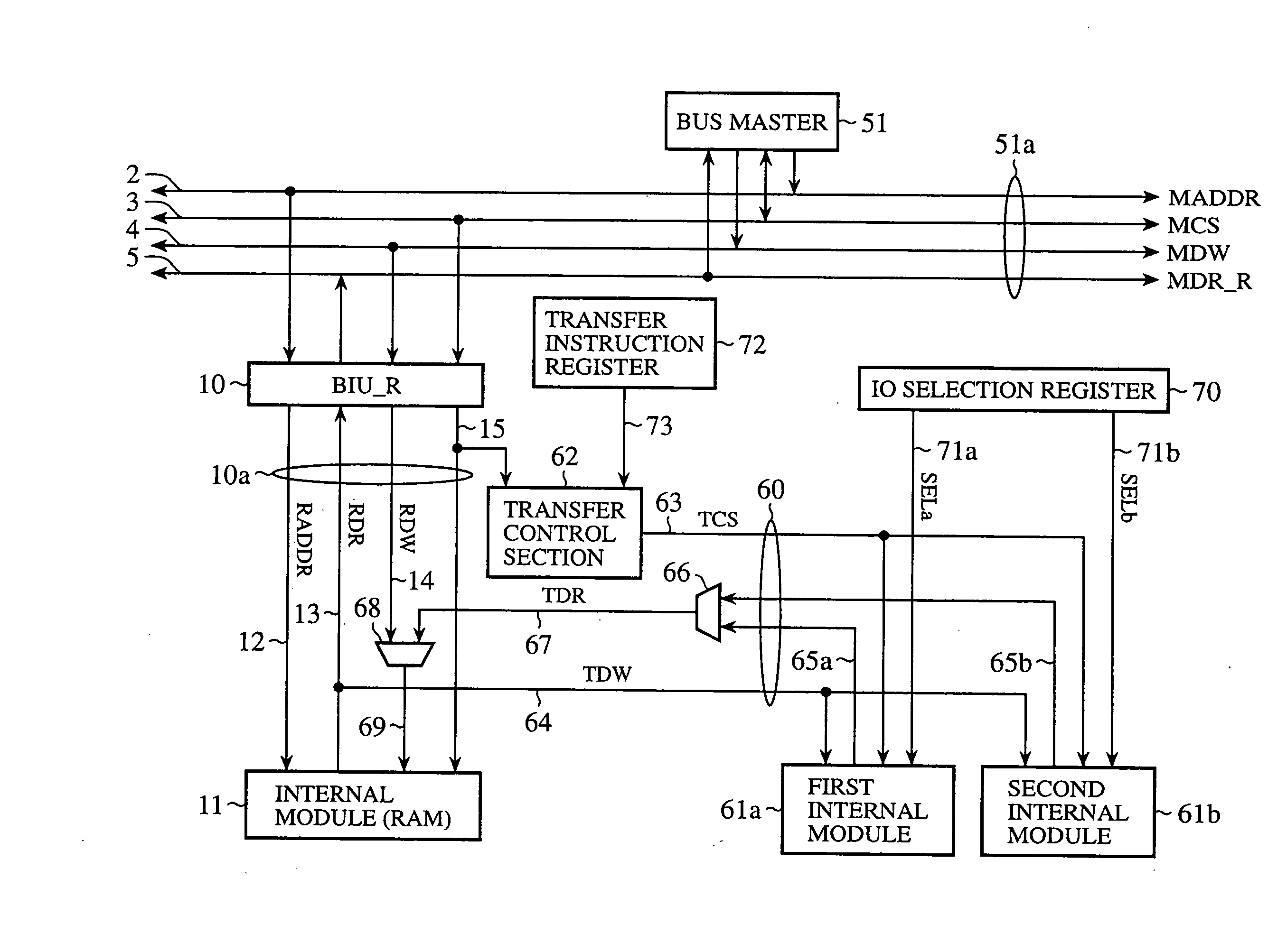
[0073]FIG. 3 is a block diagram showing the configuration of the data transfer control apparatus according to the first embodiment of the invention. The data transfer control apparatus is constructed by removing the bus master 1, the IO read data bus 6, the selector 7, the BIU_I 20, the first internal module 21a, the second internal module 21b, the selector 24 and the lines that belong to those components and by adding instead a bus master 51, a first internal ...

second embodiment

[0102] A data transfer control apparatus according to the second embodiment of the invention will then be discussed. The second embodiment is, unlike the first embodiment, directed to the data transfer control apparatus modified in such a way that the transfer instruction signal given to the transfer control section 62 is generated based on the RAM address signal RADDR supplied to the RAM 11.

[0103]FIG. 5 is a block diagram showing the configuration of the data transfer control apparatus according to the second embodiment of the invention. This data transfer control apparatus is constructed by replacing the transfer instruction register 72, one structural element of the data transfer control apparatus according to the first embodiment shown in FIG. 3, with a transfer instruction control section 80.

[0104] The transfer instruction control section 80 generates a transfer instruction signal to determine whether or not to give a transfer instruction to the transfer control section 62 ba...

third embodiment

[0113] A data transfer control apparatus according to the third embodiment of the invention will then be discussed. The third embodiment is, unlike the first embodiment, directed to the data transfer control apparatus modified in such a way that the transfer instruction signal generated by the transfer control section 62 is generated by the bus master.

[0114]FIG. 8 is a block diagram showing the configuration of the data transfer control apparatus according to the third embodiment of the invention. This data transfer control apparatus is constructed by removing the transfer instruction register 72, one structural element of the data transfer control apparatus according to the first embodiment shown in FIG. 3, and by replacing instead the bus master 51 with a new bus master 52.

[0115] The bus master 52 accesses the RAM 11, the first internal module 61a and the second internal module 61b via the BIU_R 10 and exchanges data with those components and executes data transfer between the R...


PUM


Abstract

A data transfer control apparatus has a plurality of bus slaves connected to a bus master via a bus interface unit for RAM connected to the bus master via a master bus, and a transfer bus which connects the first bus slave and plural second bus slaves in the plurality of bus slaves. When an instruction to execute data transfer via the transfer bus is given by a transfer instruction signal, data transfer between one second bus slave selected from the plural second bus slaves and the first bus slave via the transfer bus is carried out in response to a control signal contained in a control signal bus on a slave bus for RAM.

Description

CROSS REFERENCE TO RELATED APPLICATION [0001] This application is a Continuation Application of application Ser. No. 10 / 689,668, filed Oct. 22, 2003.BACKGROUND OF THE INVENTION [0002] 1. Field of the Invention [0003] The present invention relates to a data transfer control apparatus which controls data transfer to be executed among a plurality of modules formed inside, for example, a system LSI. [0004] 2. Description of the Related Art [0005] There has been known a data transfer control apparatus which is constructed inside a system LSI. This data transfer control apparatus has a plurality of bus interface units connected to a bus master via a master bus, and a plurality of bus slaves respectively connected to the bus interface units via a slave bus. The bus master is constituted by, for example, a DMA (Direct Memory Access) transfer controller. Each of the bus slaves is constituted by, for example, a RAM (Random Access Memory), an input / output module or the like. [0006] The data tr...

Claims


Application Information

Patent Timeline
Patent Type & Authority Applications(United States)
IPC IPC(8): G06F13/14G06F13/36G06F13/38G06F13/42
CPCG06F13/4226Y02B60/1235Y02B60/1228Y02D10/00
Inventor HIGUCHI, RYOHEIHIRAKI, TOSHIYUKI
Owner RENESAS ELECTRONICS CORP
Why Eureka
Try Eureka