Multiple-frequency ultrasonic test probe, inspection system, and inspection method

a multi-frequency ultrasonic and test probe technology, applied in the direction of ultrasonic/sonic/infrasonic wave generation, instruments, magnetic property measurements, etc., can solve the problems of not always being able to perform continuous scanning of structures with holes, introducing additional time and labor, and limiting the access to interior surfaces of structures, etc., to reduce the necessary sophistication of motion control systems, increase inspection speed and efficiency, and reduce costs

Active Publication Date: 2007-10-04
THE BOEING CO
View PDF16 Cites 54 Cited by
  • Summary
  • Abstract
  • Description
  • Claims
  • Application Information

AI Technical Summary

Benefits of technology

[0013] Embodiments of apparatus, systems, and methods described herein typically operate in array modes using an array of pulse echo ultrasonic transducers, thereby increasing inspection speed and efficiency while reducing cost. Such apparatus, systems, and methods are also capable of operating with a single or a plurality of pulse echo ultrasonic transducers.
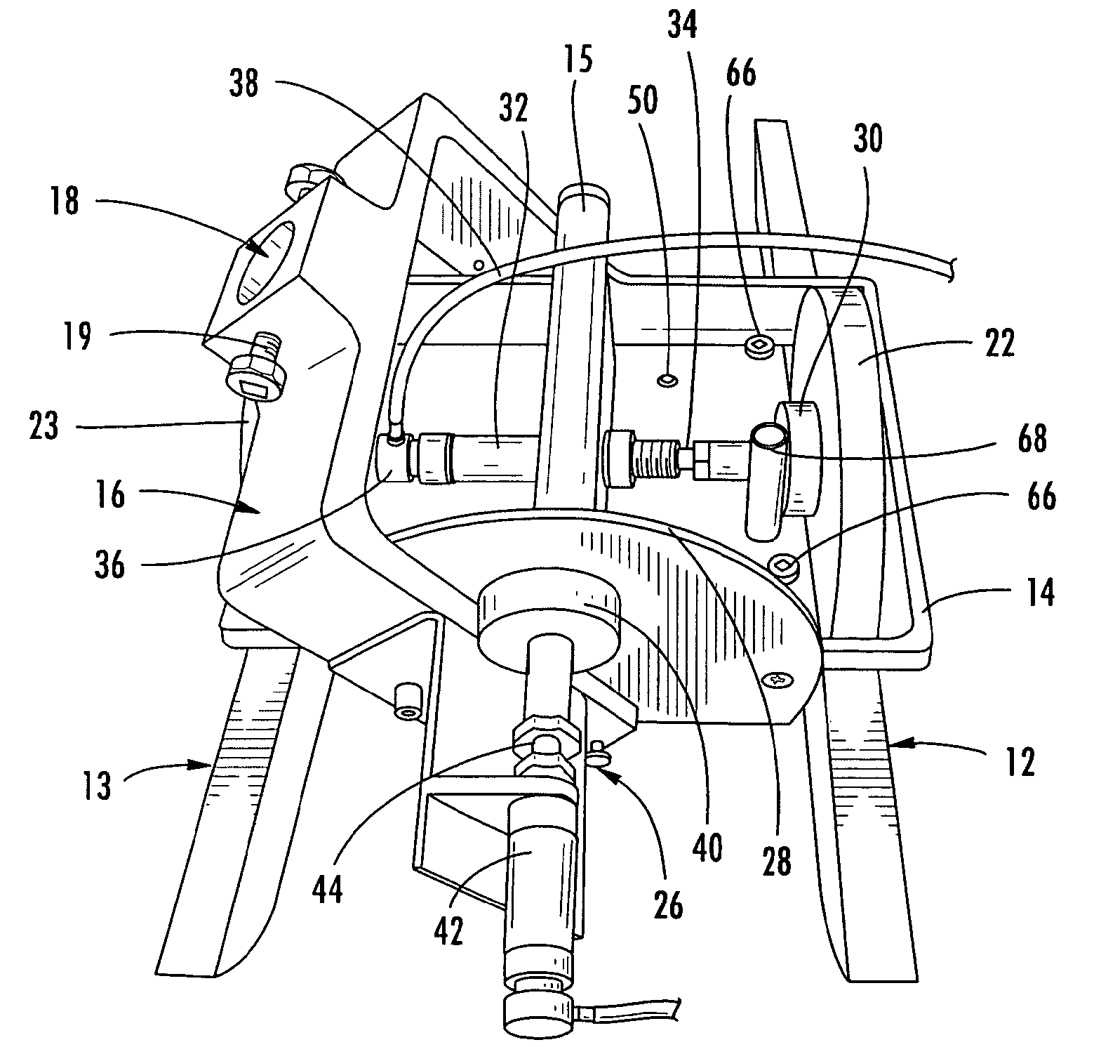
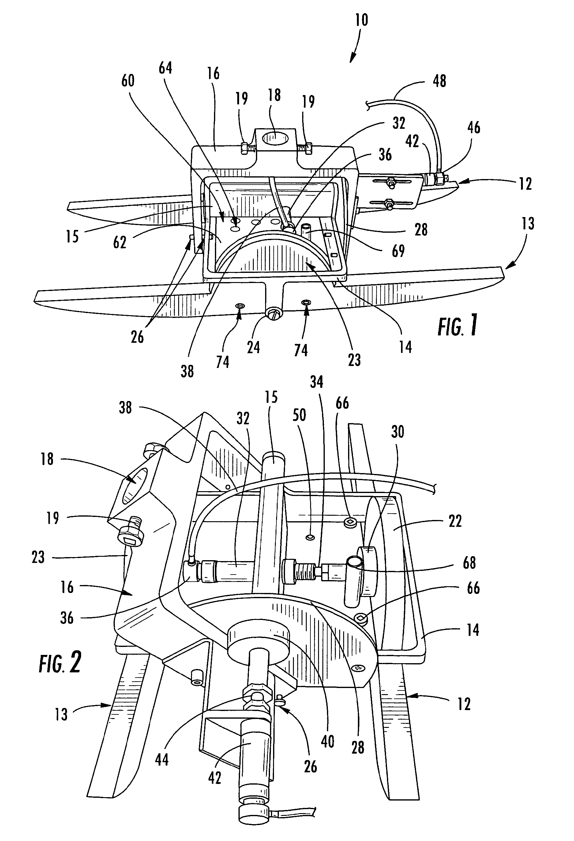
[0014] For continuous scanning applications, the embodiments of apparatus, systems, and methods permit the probe to contact and ride along the surface of the structure using one or more sled appendages, thereby reducing the necessary sophistication of a motion control system that is typically required by conventional scanning systems to maintain the probe in a predefined orientation and predefined position with respect to the surface of the structure. By allowing the probe to ride across the structure, the motion control system, or a separate device such as an extension coupler, only needs to press the probe against the structure, but does not need to know the surface contours of the structure because the act of pressing the probe against the surface combined with the sled appendages having freedom of motion and the axial motion of the probe compensate for surface contours. In addition to sled appendages, the probe may also use contact members to support the probes against the respective surfaces of the structure, such as roller bearings along the bottom of the sled appendages. The sled appendages are rotatably connected to permit freedom of motion of the sled appendages for riding along contoured surfaces. Contact with the surface ensures consistent orientation of transducers with respect to the structure for pulse echo ultrasonic inspection. Contact with the surface also permits accurate position measurement of the inspection device during continuous scanning, such as keeping an optical or positional encoder in physical and / or visual contact with the surface of the structure under inspection. Contact with the surface also permits the probe to disperse a couplant between the surface of the structure and the pulse echo ultrasonic transducers. Where a couplant is used, a probe may also include a bubbler shoe that disperses the couplant around each pulse echo ultrasonic transducer to independently couple the signal from each transducer to the surface of the part. By individually coupling each transducer to the surface of the part, the bubbler shoe compensates for when the probe travels over a hole or off an edge of the structure where all of the transducers are not over the surface of the structure. In such a manner, only the probes over the hole or off the edge of the structure will lose the coupling with the surface, but the transducers remaining over the surface of the structure will continue to be independently coupled.
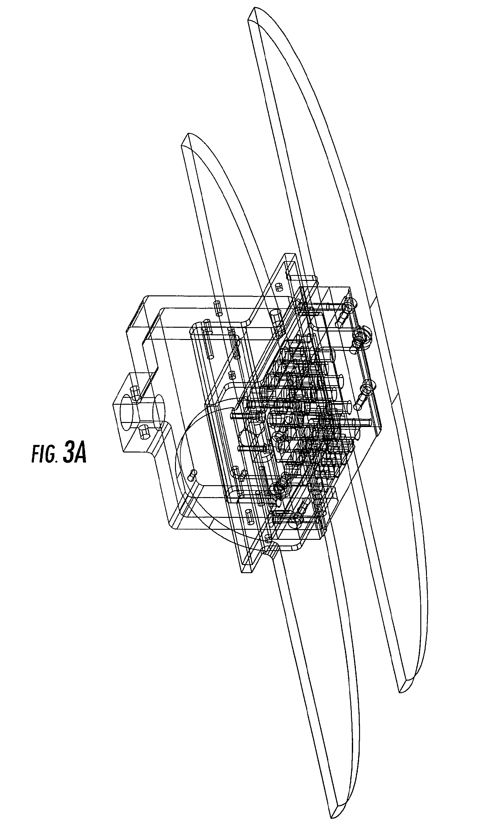
[0016] According to one embodiment, an apparatus, system, and method for non-destructive inspection of a structure employs a probe which is configured for traveling over a surface of the structure along sled appendages and using an axial braking system for traveling over holes and off edges of the structure. The probe includes at least one pulse echo ultrasonic transducer. A plurality of pulse echo ultrasonic transducers may be arranged in an array for faster and more complete scanning of the structure. If a couplant is used to couple the transducers to the surface of the structure, the probe may include a bubbler shoe to individually couple each transducer to the surface of the structure to prevent loss of coupling of transducers remaining over the surface of the structure when one or more transducers are over a hole or off an edge. The probe may also include a visual inspection sensor for providing position or optical information related to the location of the probe or transducers thereof.

Problems solved by technology

In the field, access to interior surfaces of the structure is often restricted, requiring disassembly of the structure, introducing additional time and labor.
However, it has traditionally not always been possible to perform continuous scanning of a structure with holes and off the edges of the structure.
However, for through-transmission ultrasonic inspection, a semi-automated inspection system requires access to both sides or surfaces of a structure which, at least in some circumstances, will be problematic, if not impossible, particularly for semi-automated systems that use a fixed frame for control of automated scan heads.
Conventional automated scanning systems, such as the AUSS-X system, therefore require access to both sides or surfaces of a structure for through transmission inspection which, at least in some circumstances, will be problematic, if not impossible, particularly for very large or small structures.
Further, most structures require inspection of edges around the structure and defining holes in the structure.
Multiple-pass testing in this manner is inefficient and adds cost to the testing process.
During operation, bubbles may appear in the flow chamber or flow path of the couplant, and the presence of bubbles near the ultrasonic transducers may lead to inaccurate test data.

Method used


Image

  • Multiple-frequency ultrasonic test probe, inspection system, and inspection method
  • Multiple-frequency ultrasonic test probe, inspection system, and inspection method
  • Multiple-frequency ultrasonic test probe, inspection system, and inspection method

Examples


Embodiment Construction

[0040] The following detailed description is merely illustrative in nature and is not intended to limit the embodiments of the invention or the application and uses of such embodiments. Furthermore, there is no intention to be bound by any expressed or implied theory presented in the preceding technical field, background, brief summary or the following detailed description. For the sake of brevity, conventional aspects of pulse-echo ultrasonic transducers, nondestructive testing procedures, robotics, and other aspects of the systems (and the individual operating components of the systems) may not be described in detail herein.

[0041] The contents of U.S. Pat. No. 6,722,202 (titled “Method and Apparatus for Inspecting a Structure Utilizing Magnetically Attracted Probes”), United States patent application publication No. 2006 / 0010980 A9 (titled “Non-Destructive Inspection Device for Inspecting Limited-Access Features of a Structure”), United States patent application publication No. 2...


PUM

PropertyMeasurementUnit
frequencyaaaaaaaaaa
frequencyaaaaaaaaaa
ultrasonic transduceraaaaaaaaaa

Abstract

Improved apparatus, systems, and methods for inspecting a structure are provided that use a probe having two ultrasonic transducer arrays. This enables simultaneous testing using two different test frequencies. The probe uses pulse echo ultrasonic signals at different frequencies to inspect the structure. The probe includes a support body having a fluid conduit formed therein. The fluid conduit provides flow paths for a couplant (such as water) that is used to couple the ultrasonic signals between the structure under test and the arrays. The fluid conduit is configured to quickly eject couplant and bubbles contained in the couplant.

Description

CROSS-REFERENCE TO RELATED APPLICATION [0001] This application is a continuation-in-part of U.S. patent application Ser. No. 11 / 178,637, filed Jul. 11, 2005 and published as United States patent application publication No. 2007 / 0006657 A1, which is incorporated herein by reference.TECHNICAL FIELD [0002] Embodiments of the subject matter described herein relate generally to an apparatus, system, and method for inspecting a structure and, more particularly, to an apparatus, system, and method for non-destructive pulse echo ultrasonic inspection of a structure using multiple test frequencies. BACKGROUND [0003] Non-destructive inspection (NDI) of structures involves thoroughly examining a structure without harming the structure or requiring its significant disassembly. Non-destructive inspection is typically preferred to avoid the schedule, labor, and costs associated with removal of a part for inspection, as well as avoidance of the potential for damaging the structure. Non-destructive...

Claims


Application Information

Patent Timeline
Patent Type & Authority Applications(United States)
IPC IPC(8): G01N29/34
CPCG01N29/225G01N2291/2694G01N2291/044G01N29/265
Inventor KENNEDY, JAMES C.FETZER, BARRY A.GARVEY, JEFFRY J.LITTLE, MARK L.
Owner THE BOEING CO
Why Eureka
Try Eureka