Inhaling Apparatus
a technology of inhalation apparatus and inhalation head, which is applied in the direction of inhalators, medical devices, other medical devices, etc., can solve the problems of reducing the service life of the ejection head section, reducing the risk of liquid leakage from the orifice, and reducing the adverse effect of liquid leakag
- Summary
- Abstract
- Description
- Claims
- Application Information
AI Technical Summary
Benefits of technology
Problems solved by technology
Method used
Image

Examples
embodiment 1
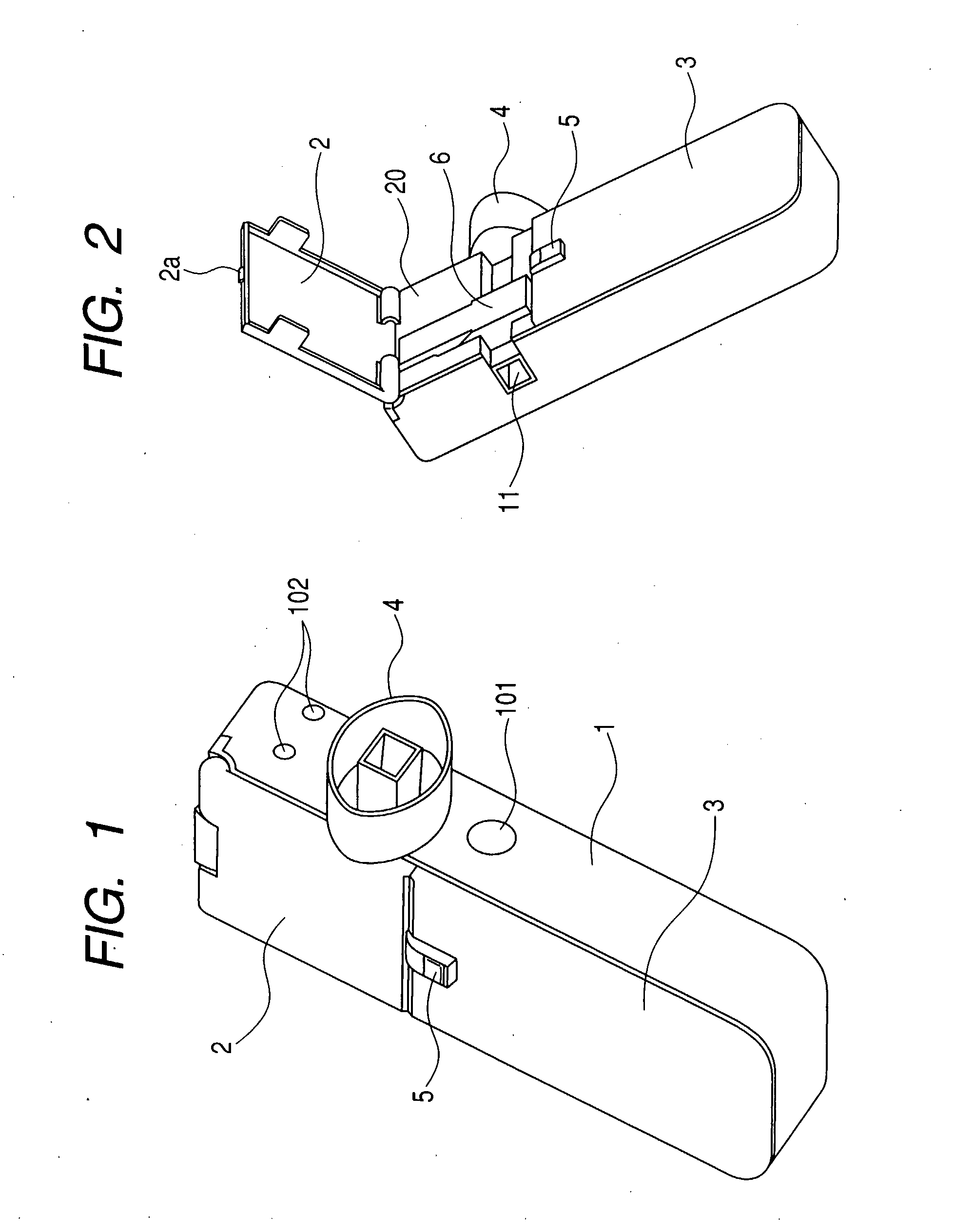
[0041]FIG. 1 is a schematic perspective view showing the outer appearance of an inhaler according to the present invention. Referring to FIG. 1, there are shown an inhaler main body 1, an access cover 2 and a front cover 3, which constitute the housing of the inhaler. In FIG. 1, reference symbol 5 denotes a lock lever urged by a spring and having a claw-like part at the front end thereof that engages with a projecting section 2a arranged at the front end of the access cover 2 in order to prevent the access cover 2 from opening in operation. As the lock lever is driven to slide downward, the access cover 2 is turned around a hinge pivot (not shown) to become open by the resilience of the access cover returning spring (not shown) that urges the access cover 2. In FIG. 1, reference symbol 101 denotes a power supply switch and reference symbol 102 denotes a display LED which indicates that an ejection head cartridge (CRG) unit or a mouthpiece, which will be described in greater detail h...
embodiment 2
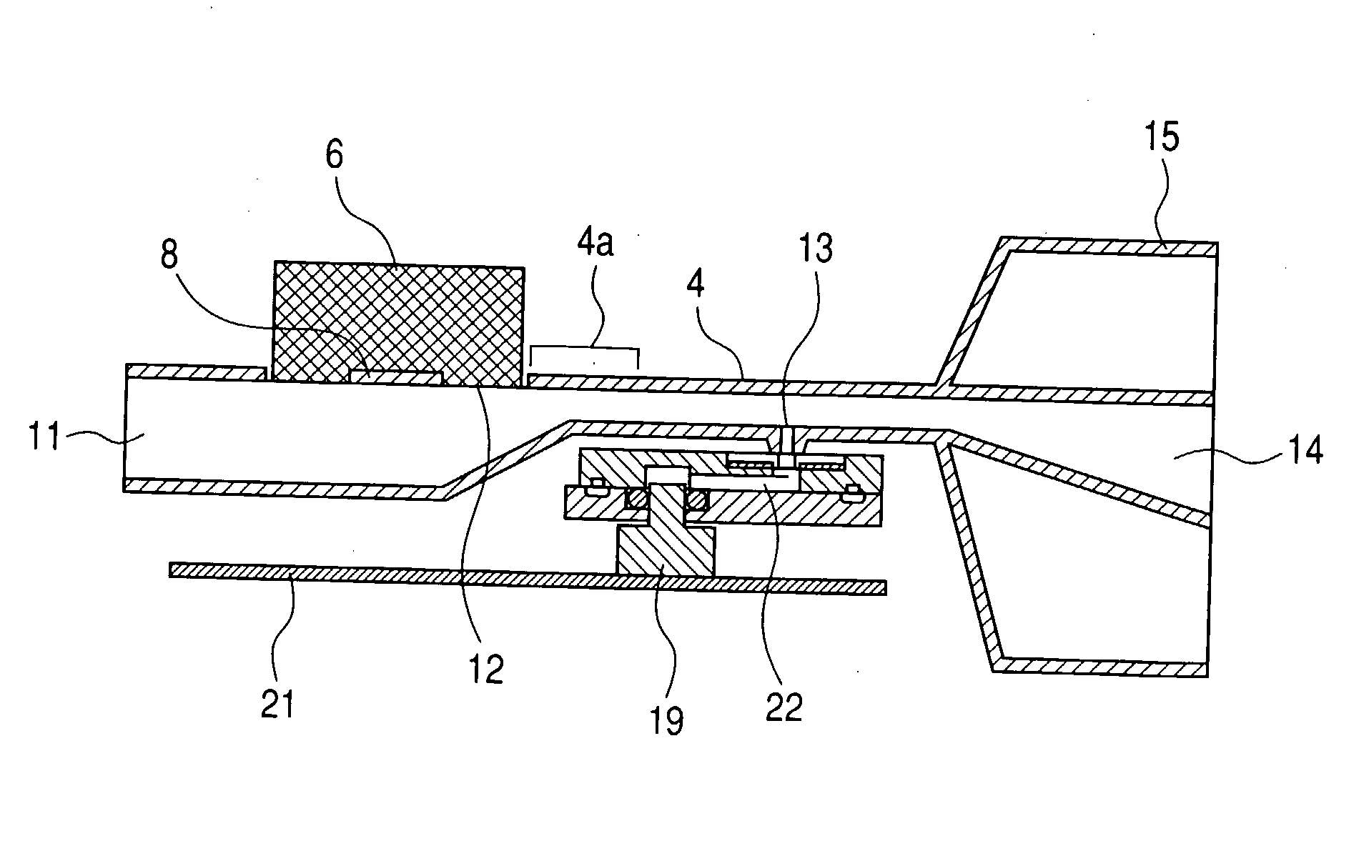
[0054]FIG. 10 is a schematic cross sectional view of Embodiment 2 of the present invention, which differs from Embodiment 1 only in terms of the configuration of the flow path to the pressure detecting section (the communication hole 13 communicating with the negative pressure sensor 19). In Embodiment 2, the communication hole 13 is arranged to the outside of the flow path exit 14 of the mouthpiece exit 15 located at the front end of the mouthpiece 4. With this arrangement, a negative pressure detecting flow path led to the negative pressure sensor 19 is completely separated from and arranged in parallel with the airflow path of the mouthpiece 4. When the mouthpiece 4 is mounted in the apparatus from the upper and front surface thereof, the mounting direction agrees with the direction in which the communication hole 13 comes tightly close to the negative pressure detecting flow path led to the negative pressure sensor 19. Thus, this arrangement is advantageous for preventing air fr...
embodiment 3
[0055]FIG. 11A and 11B show Embodiment 3 comprising a pressure alleviating means that is different from the narrowed flow path of Embodiment 1. A valve 30 having a size substantially same as the cross sectional area of the flow path of the mouthpiece 4 is rotatably arranged between the communication hole 13 led to the negative pressure sensor 19 and the liquid medical agent intake port 12 receiving the ejection head section 8 in the flow path of the mouthpiece 4. The valve 30 is constantly held to state where it substantially closes the flow path as it is made to abut a valve stopper 31 as illustrated in FIG. 11A. The valve 30 is opened as shown in FIG. 11B when the user starts an inhaling operation. While relatively strong negative pressure is generated in the flow path space at the side of the negative pressure sensor 19 at this time, such strong negative pressure is not generated in the flow path space at the side of the ejection head section 8. Thus, the net results will be same...
PUM
 Abstract
Description
Claims
Application Information
 - Generate Ideas
- Intellectual Property
- Life Sciences
- Materials
- Tech Scout
- Unparalleled Data Quality
- Higher Quality Content
- 60% Fewer Hallucinations
Browse by: Latest US Patents, China's latest patents, Technical Efficacy Thesaurus, Application Domain, Technology Topic, Popular Technical Reports.
© 2025 PatSnap. All rights reserved.Legal|Privacy policy|Modern Slavery Act Transparency Statement|Sitemap|About US| Contact US: help@patsnap.com