Photovoltaic module and method for manufacturing photovoltaic module
Active Publication Date: 2007-10-04
PANASONIC INTELLECTUAL PROPERTY MANAGEMENT CO LTD
View PDF5 Cites 15 Cited by
Summary
Abstract
Description
Claims
Application Information
AI Technical Summary
This helps you quickly interpret patents by identifying the three key elements:
Problems solved by technology
Method used
Benefits of technology
Benefits of technology
[0003] The present invention relates to a photovoltaic module and a method for manufacturing the photovoltaic module. In particular, the present invention relates to a photovoltaic module that brings improved reliability, and a method for manufacturing the photovoltaic module.
Problems solved by technology
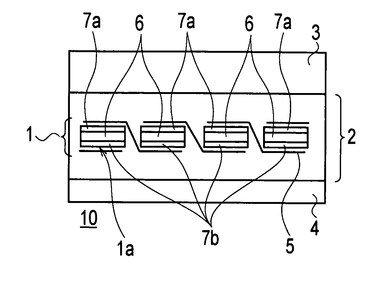
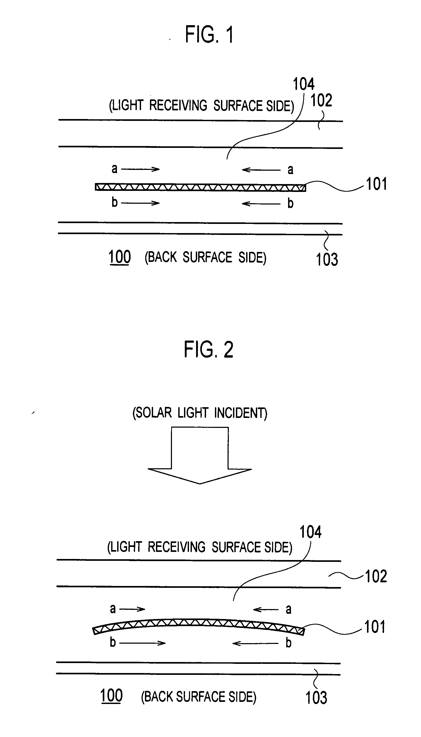
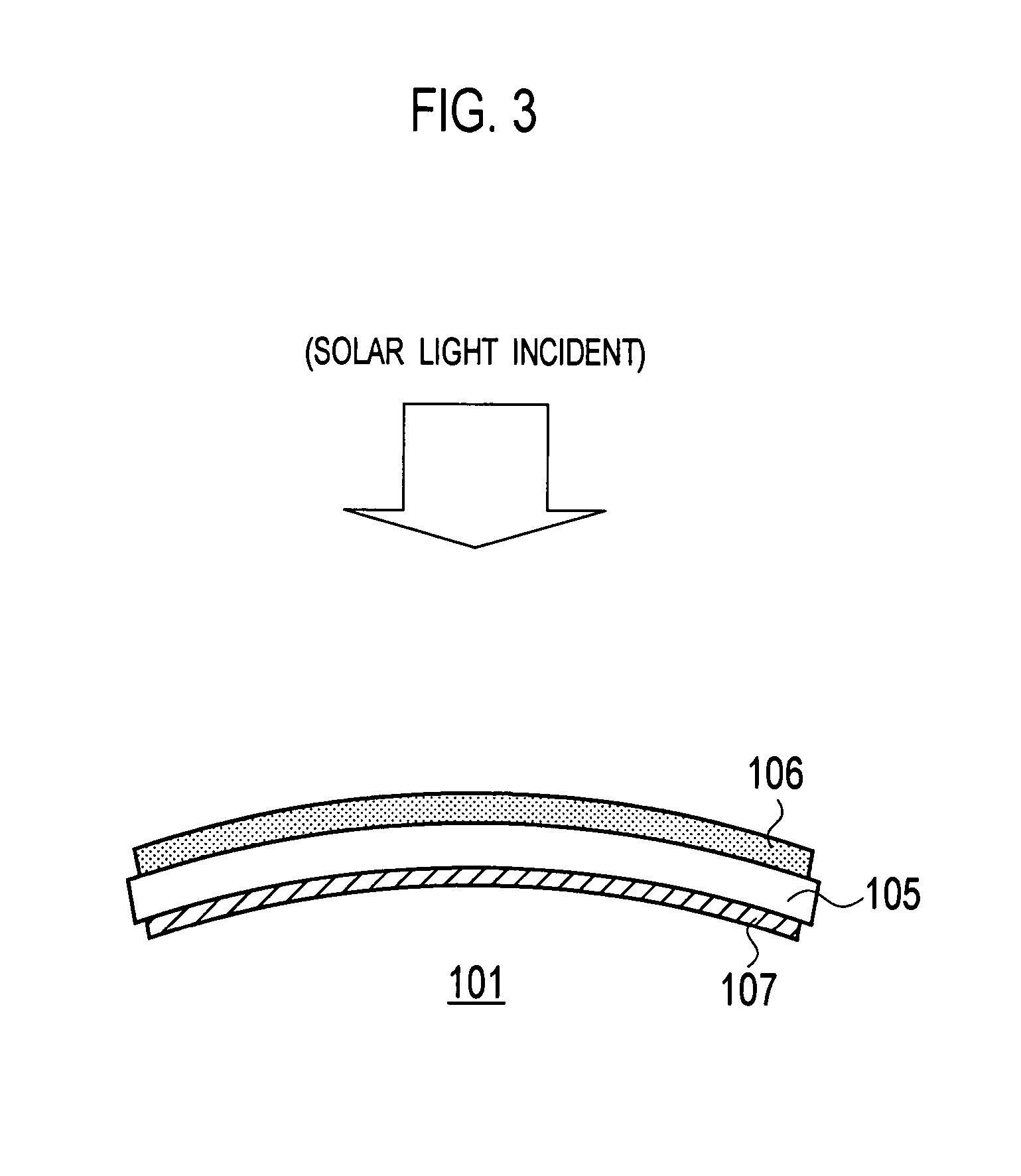
In addition, since the photovoltaic module 100 is used in the open air, and repeats receiving and not receiving the solar light, damage in the collector electrode 106 is accumulated.
Method used
Image
Click on the blue label to locate the original text in one second.
Reading with bidirectional positioning of images and text.
Examples
examples
[0080] Hereinafter, the photovoltaic module of the present invention will be described specifically by taking examples. The present invention is not limited to the below-described examples, and any appropriate modification can be made as long as the spirit and scope of the invention are not changed.
[0081] In the first place, a relationship between a temperature in the crosslinking process and the degree of cross-linkage was examined by using an EVA sheet as a sealing material sheet. Firstly, a glass plate, an EVA sheet with the thickness of 0.6 mm and a PET film were placed in this order on a mounting table of a lamination apparatus. Secondly, these materials are heated under reduced pressure at a temperature of approximately 120° C. for 10 minutes. In this way, the air was released, and the temporary adhesion was completed. Note that the temperature of approximately 120° C. is lower than the crosslinking temperature of the EVA. Thirdly, the sample in a temporary adhering state was...
example 1
[0087] A sample of an example 1 was fabricated by performing the laminating process for 10 minutes, the first curing process for 0 minute, and the second curing process for 45 minutes.
[0088] In other words, in the sample of the example 1, the sealing material on the light receiving surface side was heated at the temperature of 150° C. for 45 minutes, while the sealing material on the back surface side was heated at the temperature of 150° C. for 0 minute. Hence, from the foregoing result shown in Table 2, it can be assumed that the gel fraction of the sealing material on the light receiving surface side is approximately 87%, and that the gel fraction of the sealing material on the back surface side is approximately 0%.
example 2
[0089] A sample of an example 2 was fabricated by performing the laminating process for 10 minutes, the first curing process for 5 minutes, and the second curing process for 40 minutes.
[0090] In other words, in the sample of the example 2, the sealing material on the light receiving surface side was heated at the temperature of 150° C. for 45 minutes, while the sealing material on the back surface side was heated at the temperature of 150° C. for 5 minutes. Hence, from the foregoing result shown in Table 2, it can be assumed that the gel fraction of the sealing material on the light receiving surface side is approximately 87%, and that the gel fraction of the sealing material on the back surface side is approximately 13%.
PUM
Abstract
An object of the present invention is to provide a photovoltaic module that achieves a reduction in adverse influence of damage accumulated in a collector electrode provided on the light receiving surface side, and a method for manufacturing the photovoltaic module. To this end, in a photovoltaic module of the present invention, the degree of cross-linkage of the second region of the sealing material that is in contact with the back surface of the solar cell is smaller than that of the first region of the sealing material that is in contact with the light receiving surface of the solar cell.
Description
CROSS REFERENCE TO RELATED APPLICATIONS [0001] This application is based upon and claims the benefit of priority from prior Japanese Patent Application No.2006-095647, filed on Mar. 30, 2006; and prior Japanese Patent Application No.2007-029661, filed on Feb. 8, 2007; the entire contents of which are incorporated herein by reference. BACKGROUND OF THE INVENTION [0002] 1. Technical Field of the Invention [0003] The present invention relates to a photovoltaic module and a method for manufacturing the photovoltaic module. In particular, the present invention relates to a photovoltaic module that brings improved reliability, and a method for manufacturing the photovoltaic module. [0004] 2. Description of the Related Art [0005] A photovoltaic system directly converts the solar light, which is clean and inexhaustibly supplied, into electricity. For this reason, the photovoltaic system is expected as a new energy source. [0006] Here, in a case of a solar cell constituting the photovoltaic ...
Claims
Application Information
Patent Timeline
Application Date:The date an application was filed.
Publication Date:The date a patent or application was officially published.
First Publication Date:The earliest publication date of a patent with the same application number.
Issue Date:Publication date of the patent grant document.
PCT Entry Date:The Entry date of PCT National Phase.
Estimated Expiry Date:The statutory expiry date of a patent right according to the Patent Law, and it is the longest term of protection that the patent right can achieve without the termination of the patent right due to other reasons(Term extension factor has been taken into account ).
Invalid Date:Actual expiry date is based on effective date or publication date of legal transaction data of invalid patent.

