Pneumatic tire

a technology of pneumatic tires and pneumatic wheels, which is applied in the field of pneumatic tires, can solve the problems of increasing the resistance of tires and inability to ensure safety when used, and achieve the effects of reducing electric resistance, preventing static electricity generation between the road surface and tires, and improving safety

Inactive Publication Date: 2007-10-04
SUMITOMO RUBBER IND LTD
View PDF16 Cites 13 Cited by
  • Summary
  • Abstract
  • Description
  • Claims
  • Application Information

AI Technical Summary

Benefits of technology

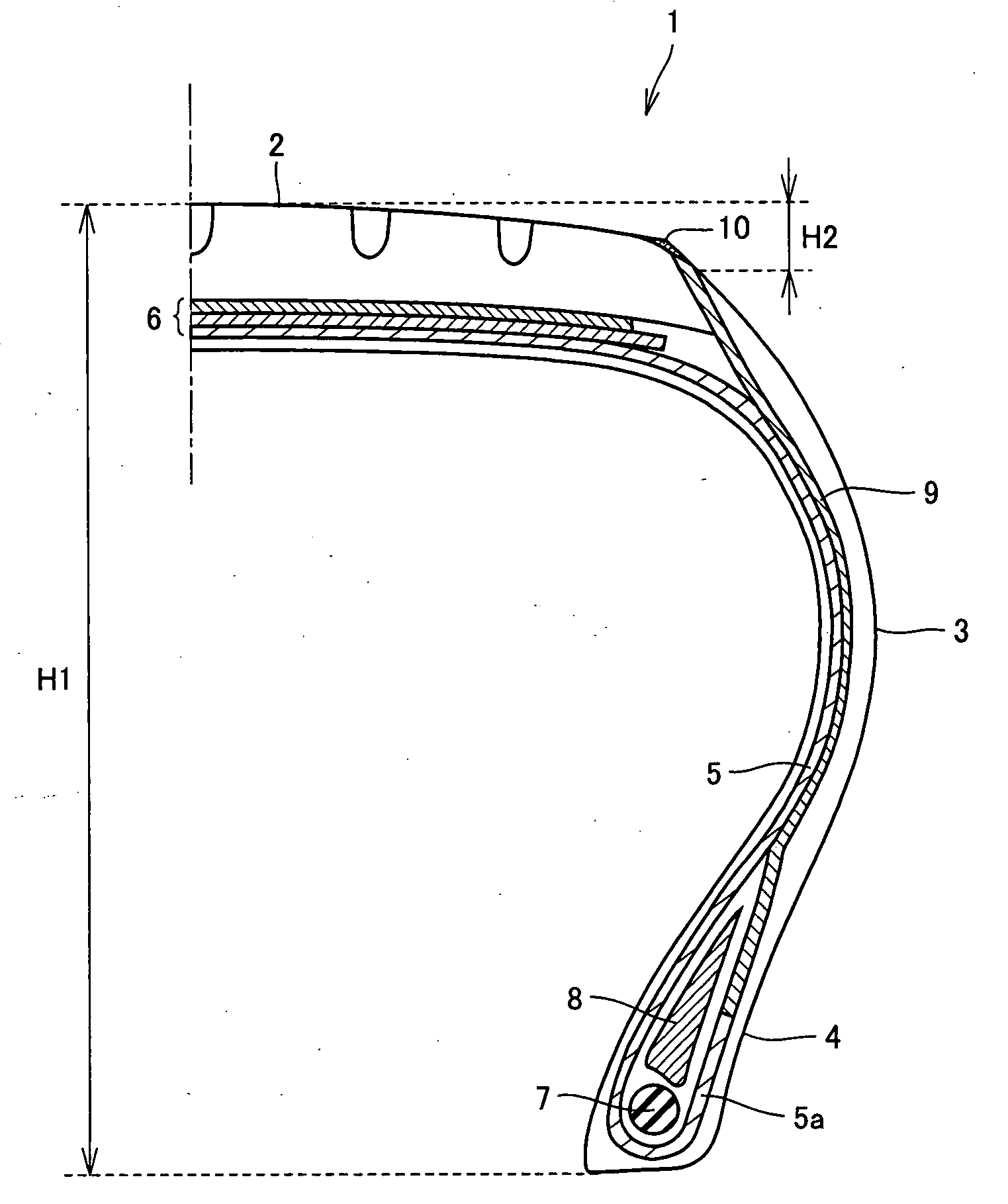
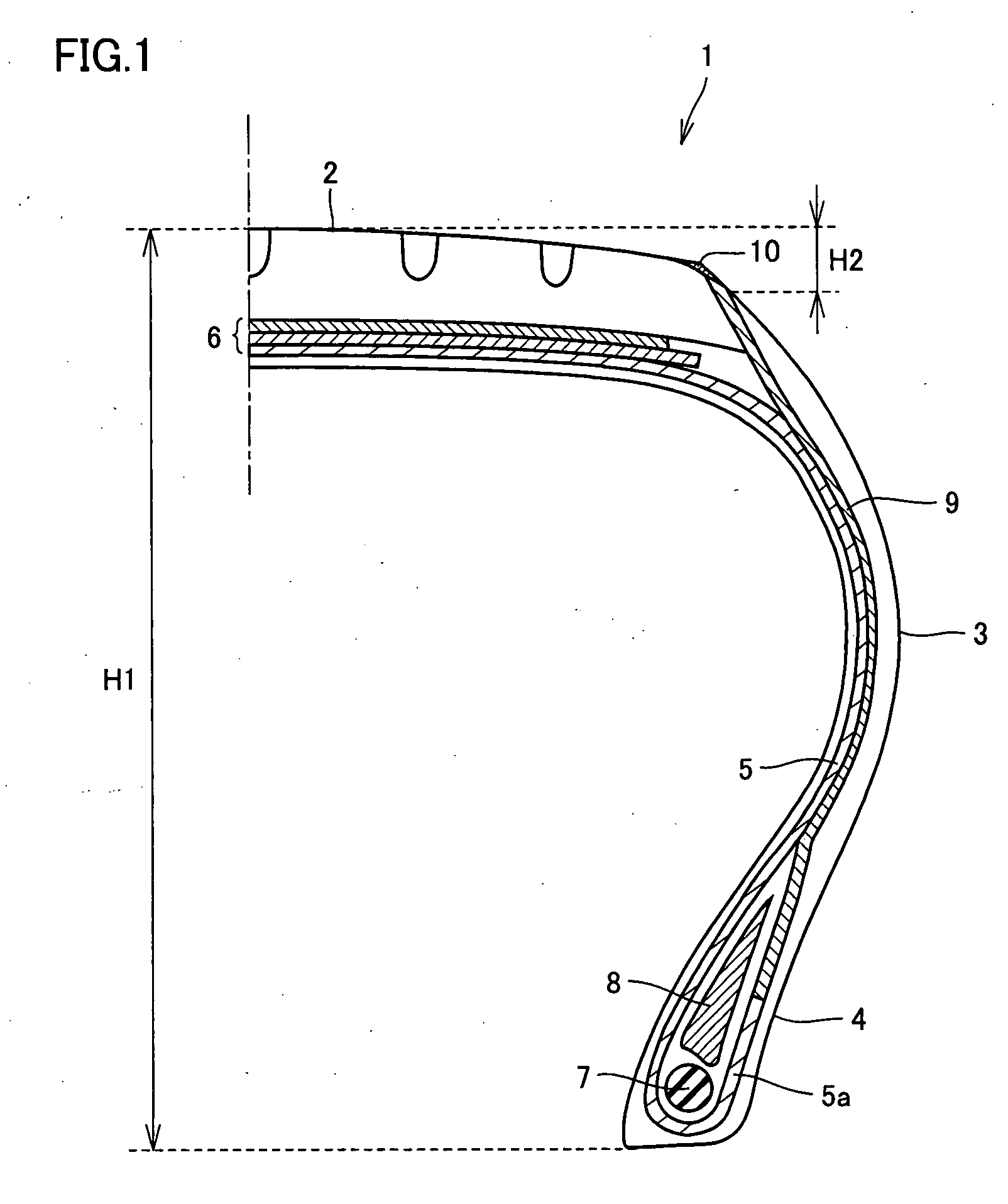
[0011]The objective of the present invention is to provide a pneumatic tire in which the above-described problems are solved, the generation of static electricity between the road surface and the tire is well prevented, and safety is improved when used by lowering electric resistance.

Problems solved by technology

However, in the case of compounding silica in a large amount, the electric resistance of the tire increases and for example there is a case that a spark due to static electricity is generated and fuel is ignited when fuel is supplied to a vehicle, and there is a problem that safety cannot be assured when used.

Method used


Image

  • Pneumatic tire
  • Pneumatic tire
  • Pneumatic tire

Examples


examples

[0058]The present invention is explained in detail by giving examples below. However, the present invention is not limited to these.

[0059]After kneading the components except for sulfur and a vulcanization accelerator in the compounding components shown in Table 1 using a seal type Banbury mixer at 150° C. for 5 minutes, sulfur and the vulcanization accelerator were added and mixed more at 80° C. for 5 minutes using a biaxial open roll, and the rubber compositions A to G for the conductive layer were prepared through a extrusion process and a calendar process with the usual method.

[0060]After kneading the components except for sulfur and a vulcanization accelerator in the compounding components shown in Table 2 using a seal type Banbury mixer at 150° C. for 5 minutes, sulfur and the vulcanization accelerator were added and mixed more at 80° C. for 5 minutes using a biaxial open roll, and the rubber composition H for the rubber cement layer was prepared through a extrusion process an...


PUM

PropertyMeasurementUnit
volume resistivityaaaaaaaaaa
thicknessaaaaaaaaaa
thicknessaaaaaaaaaa

Abstract

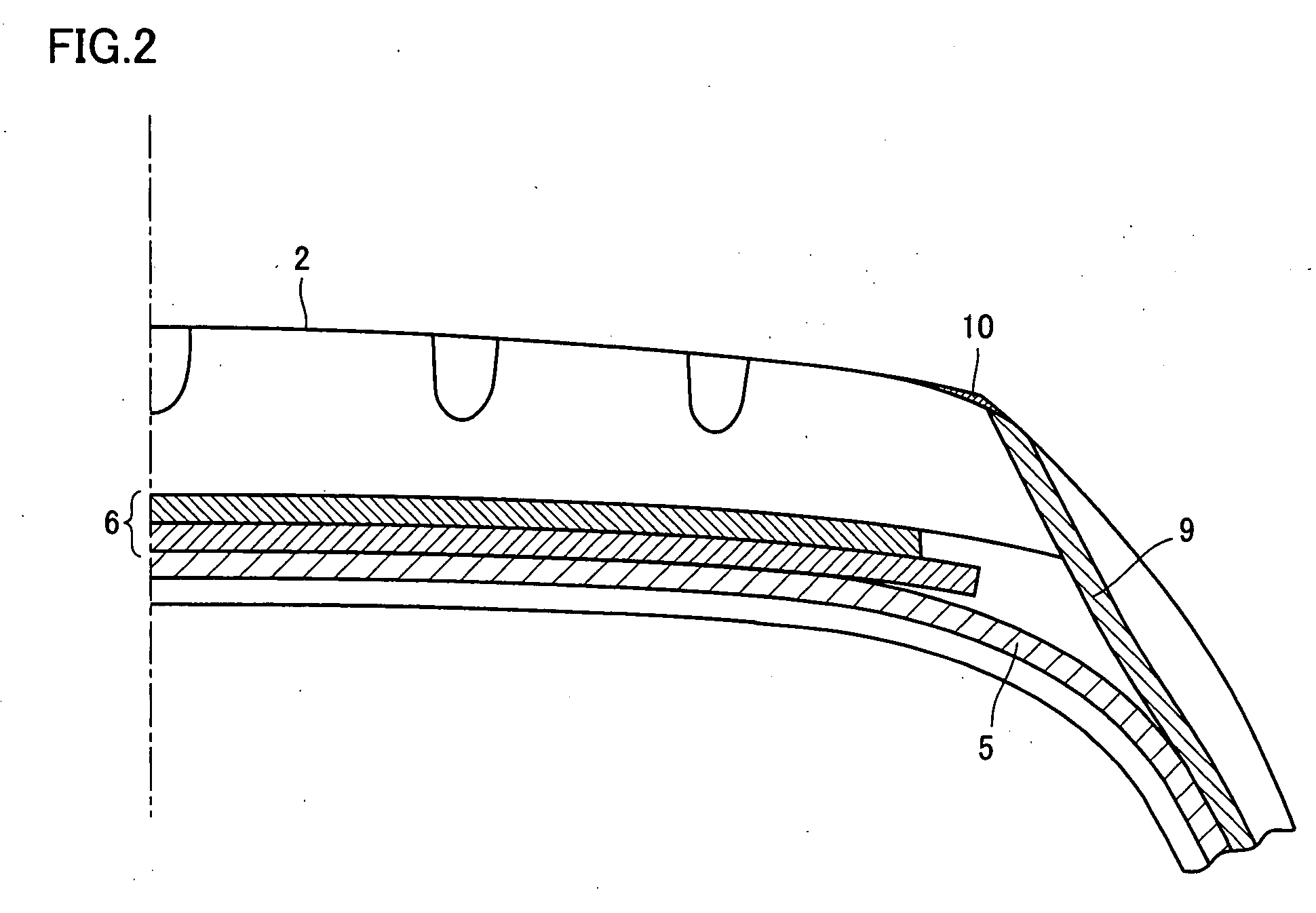
A pneumatic tire is equipped with at least a tread part, a sidewall part, a bead part, and a carcass extending from tread part through sidewall part to bead part, and provided with a breaker part on the outside of carcass in the radial direction of the tire. The volume resistivity of each of a tread rubber, a sidewall rubber, a breaker rubber, and a carcass rubber formed in the tread part, the sidewall part, the breaker part, and the carcass respectively is set to 1×10¹² Ω·cm or more. A conductive layer having volume resistivity of 1×10¹¹ Ω·cm or less is provided between a carcass ply constituting the carcass and the sidewall rubber and has an exposed part to the tire surface. A rubber cement layer contacting with at least a part of the exposed part of the conductive layer and at least a part of the region that becomes a grounding surface in the tread part to the road surface is provided.

Description

[0001]This nonprovisional application is based on Japanese Patent Application No. 2006-103349 filed with the Japan Patent Office on Apr. 4, 2006, the entire contents of which are hereby incorporated by reference.BACKGROUND OF THE INVENTION[0002]1. Field of the Invention[0003]The present invention relates to a pneumatic tire that can reduce an electric resistance and improve the safety in use.[0004]2. Description of the Background Art[0005]In recent years, various methods have been proposed using silica for example in the tread part of a tire, and furthermore also in the breaker part and the sidewall part as other members of the tire in order to reduce the rolling resistance of the tire and to maintain wet grip performance. However, in the case of compounding silica in a large amount, the electric resistance of the tire increases and for example there is a case that a spark due to static electricity is generated and fuel is ignited when fuel is supplied to a vehicle, and there is a p...

Claims


Application Information

Patent Timeline
Patent Type & Authority Applications(United States)
IPC IPC(8): B60C19/08
CPCB60C19/08C08K3/04C08K2201/001C08L21/00C08L71/00C08L2666/14Y10S152/02
Inventor MIZUNO, YOUICHIUCHIDA, MAMORU
Owner SUMITOMO RUBBER IND LTD
Why Eureka
Try Eureka