Fixing device

a technology for fixing devices and heat sinks, which is applied in the direction of machine supports, machine support, and other domestic objects, can solve the problems of wasting space reserved for fans, affecting the expansion of the server, and unable to design the space of the case according to the number, etc., and achieves high maintenance costs, convenient operation, and quick performance

Inactive Publication Date: 2007-10-04
INVENTEC CORP
View PDF13 Cites 6 Cited by
  • Summary
  • Abstract
  • Description
  • Claims
  • Application Information

AI Technical Summary

Benefits of technology

[0007] In light of the above prior-art drawbacks, a primary objective of the present invention is to provide a fixing device that can be designed according to the number of required heat sinks, so as to flexibly use the space of an electronic device.
[0008] Another objective of the present invention is to provide a fixing device that does not require any tools for the detachment process, by which the detachment process can be completed immediately.
[0009] A further objective of the present invention is to provide a fixing device that allows partial replacement, so as to reduce maintenance costs.
[0014] Due to the design of the connection of the first connecting portion and the second connecting portion, the fixing device proposed in the present invention can be designed depending on the number of heat sinks required by the electronic device. Thus, in comparison to the prior-art technique, the fixing device proposed in the present invention is able to eliminate the drawback that the limited space of the electronic device is occupied by the space provided for heat sinks. Also, the fixing device proposed in the present invention does not require any tools to perform a detachment process, such that the difficulties encountered in performing the detachment process that occurred in the prior-art technique can be eliminated, and the detachment process can be quickly performed by a user. Further, as the present invention proposes a detachable fixing device which can be conveniently operated, an assembling process can be easily performed and partial replacement can be achieved according to which part of the fixing device is aged or damaged, for example, the first fixing member or the second fixing member. Therefore, the prior-art problem regarding high maintenance costs caused by the required replacement of the overall structure can be solved, so as to reduce the maintenance cost and improve industrial applicability.
[0015] Accordingly, the fixing device proposed in the present invention can be designed according to the number of required heat sinks, so as to flexibly use the space of the electronic device. Moreover, the fixing device proposed in the present invention does not require any tools to perform the detachment process, so as to simplify the assembly process, shorten the time required for the assembly process, and reduce maintenance costs. Therefore, the present invention is able to eliminate prior-art drawbacks and improve industrial utilization.

Problems solved by technology

Also, as a fan may need to be replaced due to a breakdown after being used over a period of time, the fan is usually installed in the case of the electronic device using a detachable method.
However, when the amount of heat generated does not require the case to be fully installed with fans, the space reserved for fans is wasted.
In other words, the foregoing patents are unable to design the space of the case according to the number of fans.
Thus, the case tends to occupy the limited space of the electronic device, such that the expandability of the server can be impaired by such an inflexible design.
Furthermore, referring to Taiwan Patent No. 584264, which discloses a method for fixing the fan in the case using tools, the requirement for tools is a limiting factor and the detachment process can be time-consuming.
Additionally, referring to Taiwan Patent No. 578995, the fixing element being disclosed is very complex in structure and the alignment process during assembly is very difficult.
Moreover, when a large number of elements are used inside the case of the server and thus occupying the limited space of the electronic device, the detachment process is especially difficult, regardless of whether using tools during assembly / disassembly or not.
Moreover, if the foregoing prior-art fixing device is damaged, the overall structure needs to be replaced and other elements cannot be re-used, so that the maintenance of the electronic device is very cost-ineffective.
Also, as the assembly process required after elements are replaced is very complex, the production cost and the difficulty of the assembling process are increased as a consequence.

Method used


Image

  • Fixing device
  • Fixing device
  • Fixing device

Examples


Embodiment Construction

[0021] The present invention is described in the following with specific embodiments, so that one skilled in the pertinent art can easily understand other advantages and effects of the present invention from the disclosure of the invention. The present invention may also be implemented and applied according to other embodiments, and the details may be modified based on different views and applications without departing from the spirit of the invention.

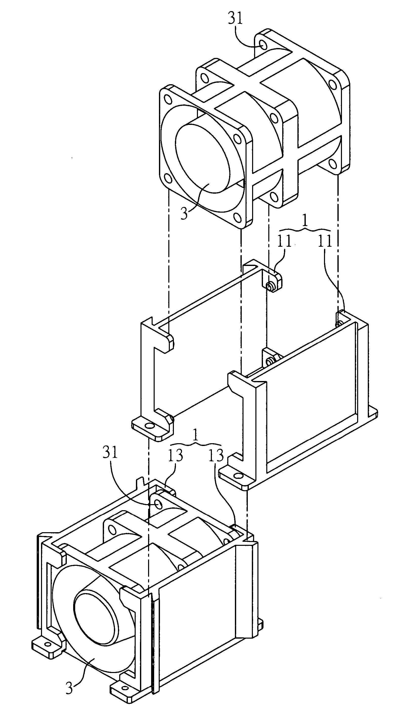
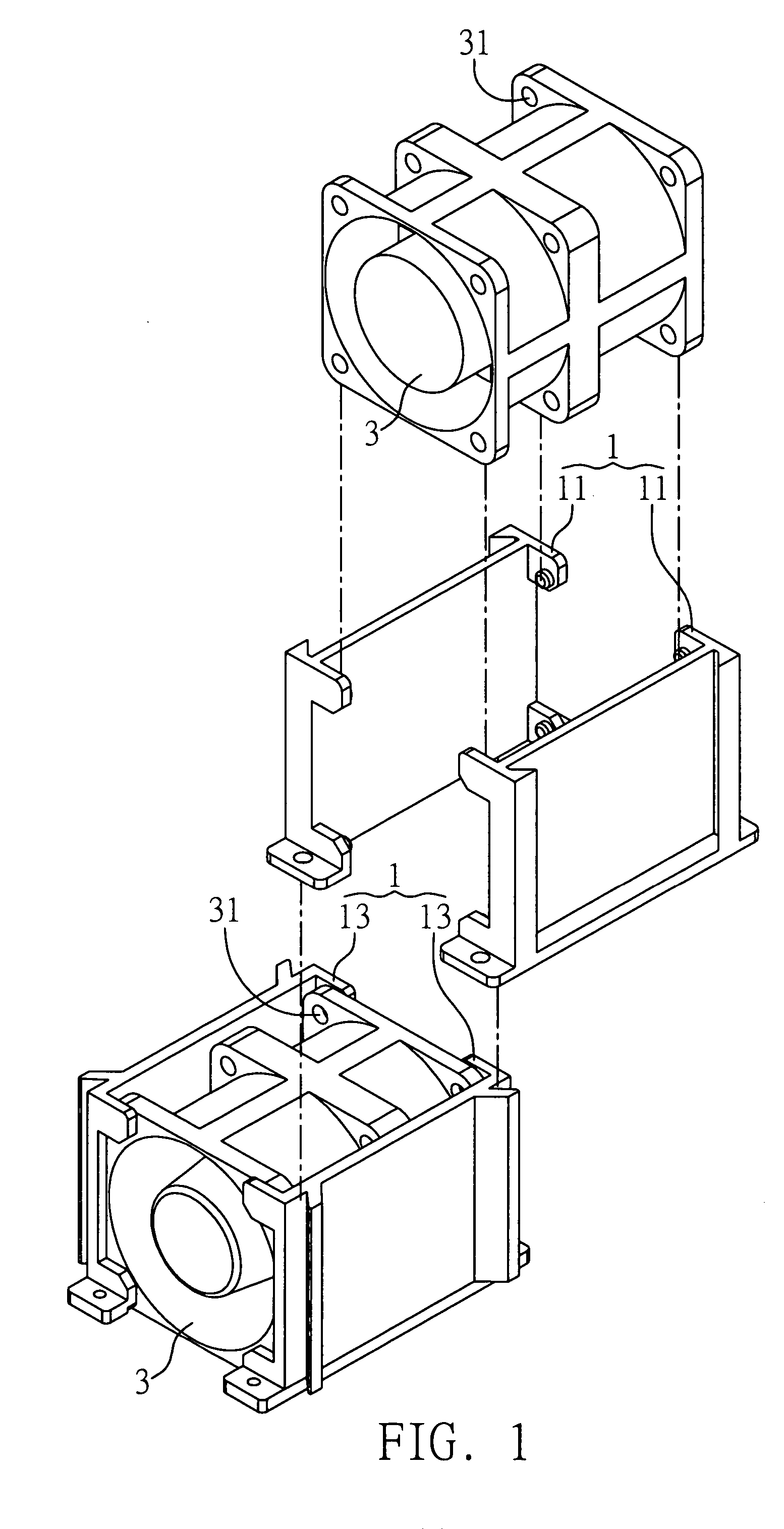
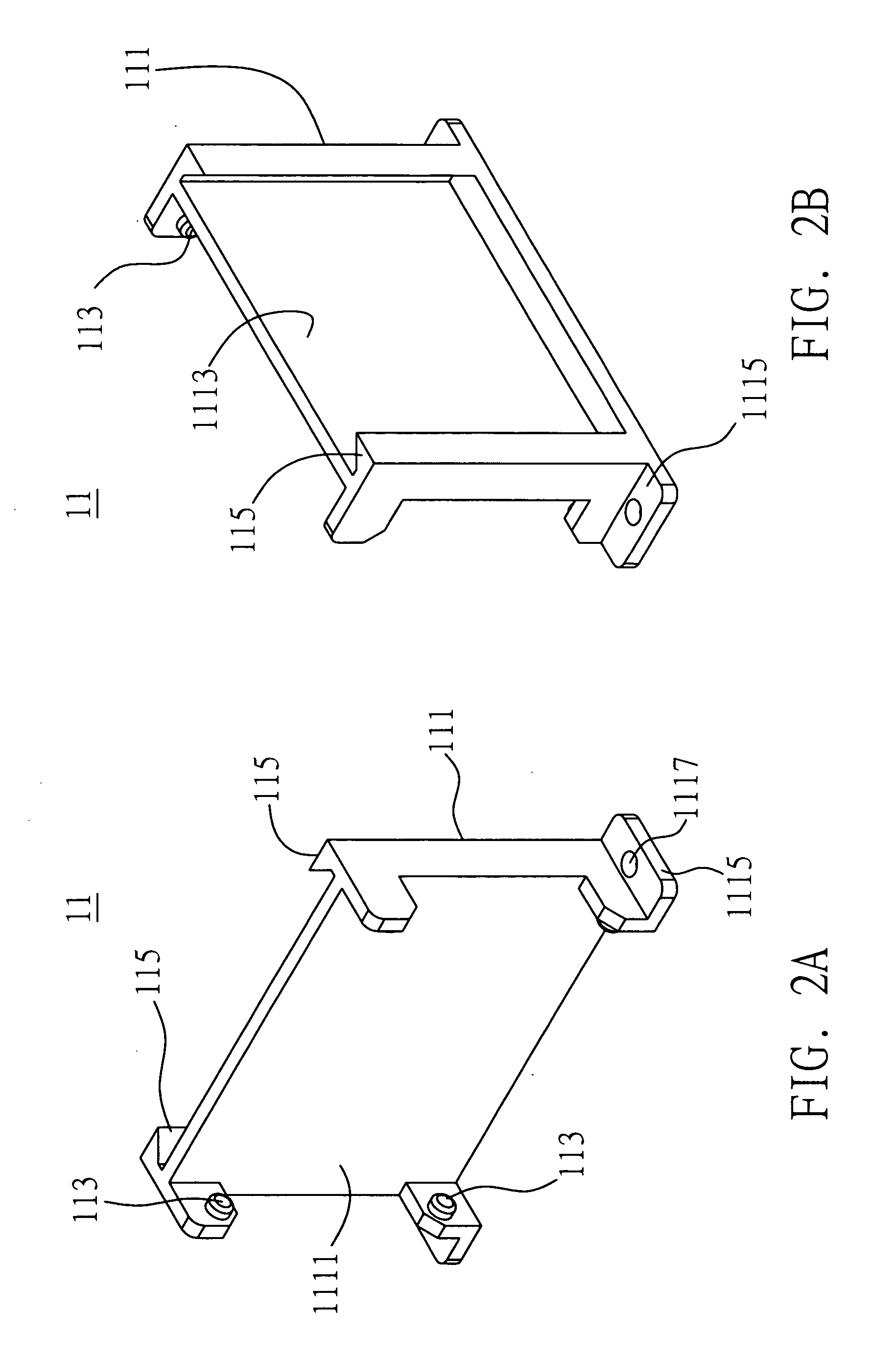
[0022]FIG. 1 to FIG. 4B are perspective diagrams showing a fixing device 1 according to a preferred embodiment of the present invention. Referring to FIG. 1, the fixing device 1 comprises a first fixing member 11 and a second fixing member 13. Also, as shown in FIG. 1, the fixing device 1 proposed in the present invention serves to fix a heat sink 3 in an electronic device (not shown in the figure). The heat sink 3 comprises a buttonhole 31. A fan for an electronic device such as a server serves to provide further description of the h...


PUM


Abstract

A fixing device for fixing a heat sink in an electronic device is proposed. The fixing device includes a first fixing member and a second fixing member both for being mounted to the electronic device. The first fixing member and the second fixing member respectively further include a first fixing portion and a second fixing portion both for fixing two surfaces of the heat sink, and a first connecting portion and a second connecting portion, allowing the second connecting portion of the fixing device to be coupled to the first connecting portion of another fixing device mounted to another heat sink, so as to connect at least two heat sinks to each other. Therefore, the fixing device can be provided according to the number of required heat sinks, so as to eliminate prior-art drawbacks.

Description

FIELD OF THE INVENTION [0001] The present invention relates to a technique for fixing a heat sink, and more particularly, to a fixing device for fixing a heat sink in a case of an electronic device. BACKGROUND OF THE INVENTION [0002] A heat sink such as a fan is usually provided in a case of an electronic device such as a server, a computer, etc., so as to prevent abnormal operation of the system caused by an excessively high temperature during the operation. As the amount of heat needing to be dissipated has gradually gone up with higher clock speeds and higher integration, larger or multiple heat sinks are often required and such heat sinks often employ fans. Also, as a fan may need to be replaced due to a breakdown after being used over a period of time, the fan is usually installed in the case of the electronic device using a detachable method. [0003] Take the example of an electronic device such as a server, a number of fans are usually provided in the server case having a numb...

Claims


Application Information

Patent Timeline
Patent Type & Authority Applications(United States)
IPC IPC(8): F16M5/00
CPCH01L23/4006H01L2023/4056H01L2023/4087H05K7/20172H01L2924/0002H01L2924/00
Inventor TSAI, TSUNG-BIN
Owner INVENTEC CORP
Why Eureka
Try Eureka