Method for expelling gas positioned between a substrate and a mold

a technology of gas expelling and molds, applied in the field of nanofabrication of structures, can solve the problems of low fidelity of features formed, pattern distortion of solidified layers, and non-uniform thickness of residual layers of solidified layers

Inactive Publication Date: 2007-10-04
CANON KK
View PDF99 Cites 62 Cited by
  • Summary
  • Abstract
  • Description
  • Claims
  • Application Information

AI Technical Summary

Problems solved by technology

To that end, gases may be present between the template and the substrate and within the formable liquid which may result in, inter alia, pattern distortion of the solidif

Method used


Image

  • Method for expelling gas positioned between a substrate and a mold
  • Method for expelling gas positioned between a substrate and a mold
  • Method for expelling gas positioned between a substrate and a mold

Examples


Embodiment Construction

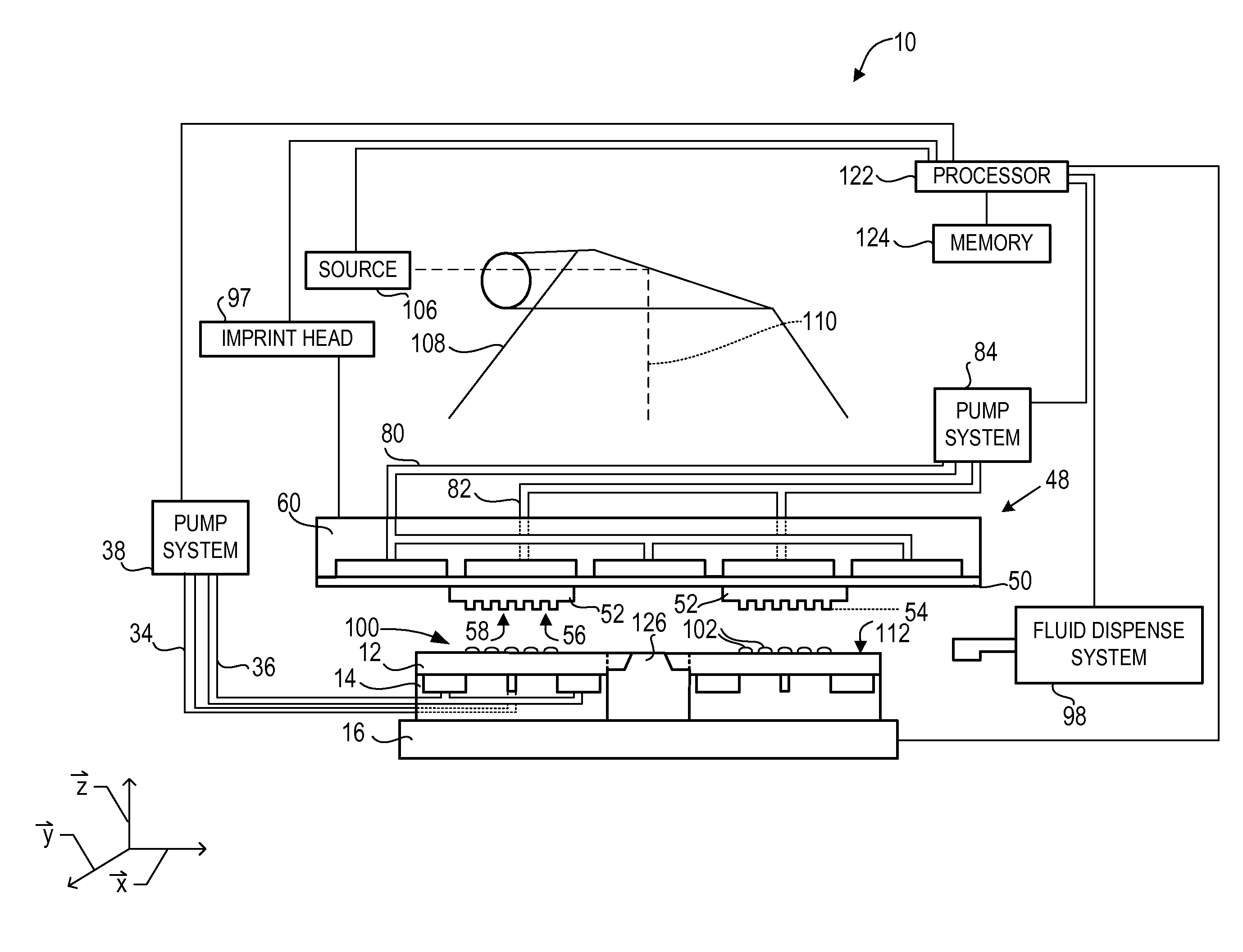
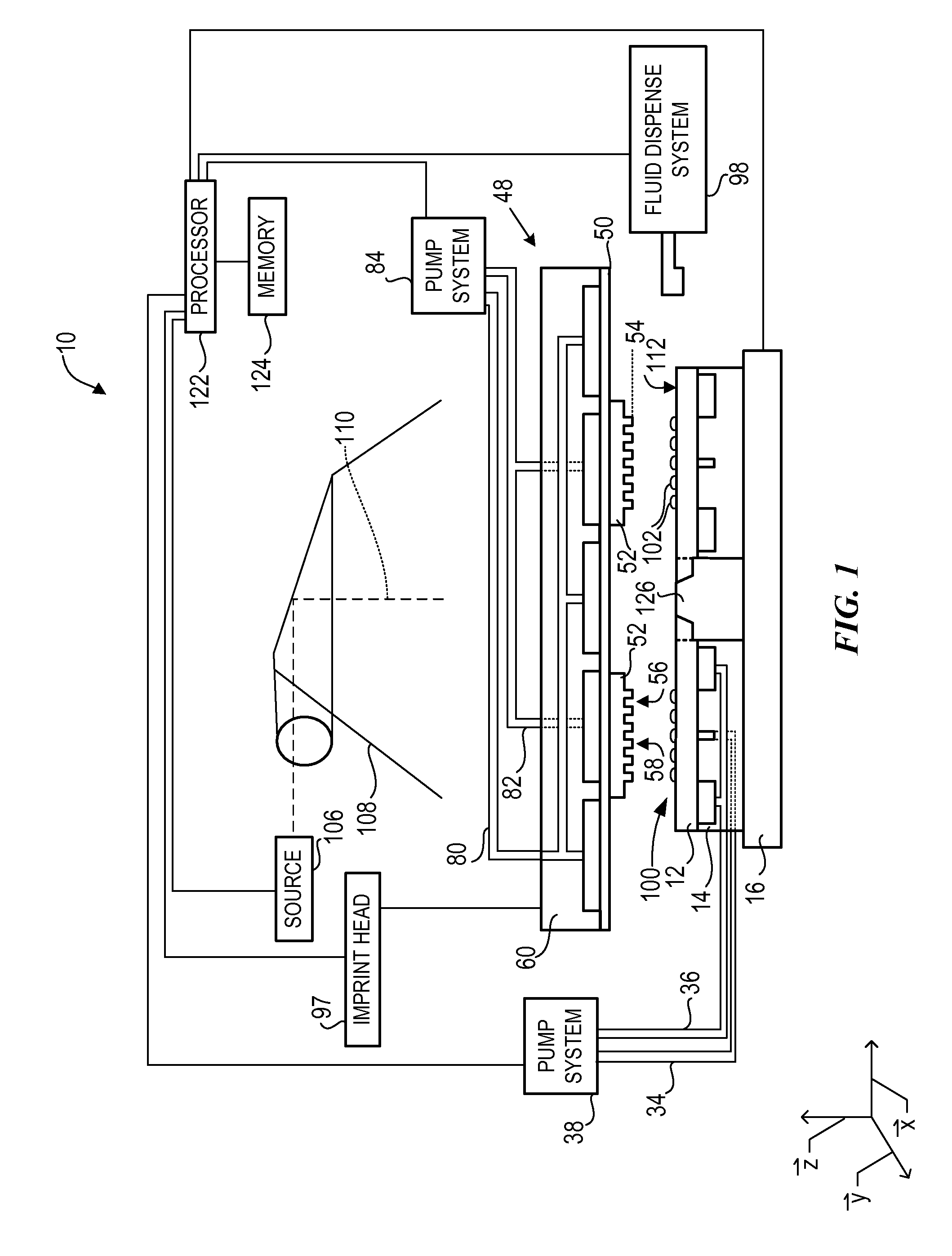
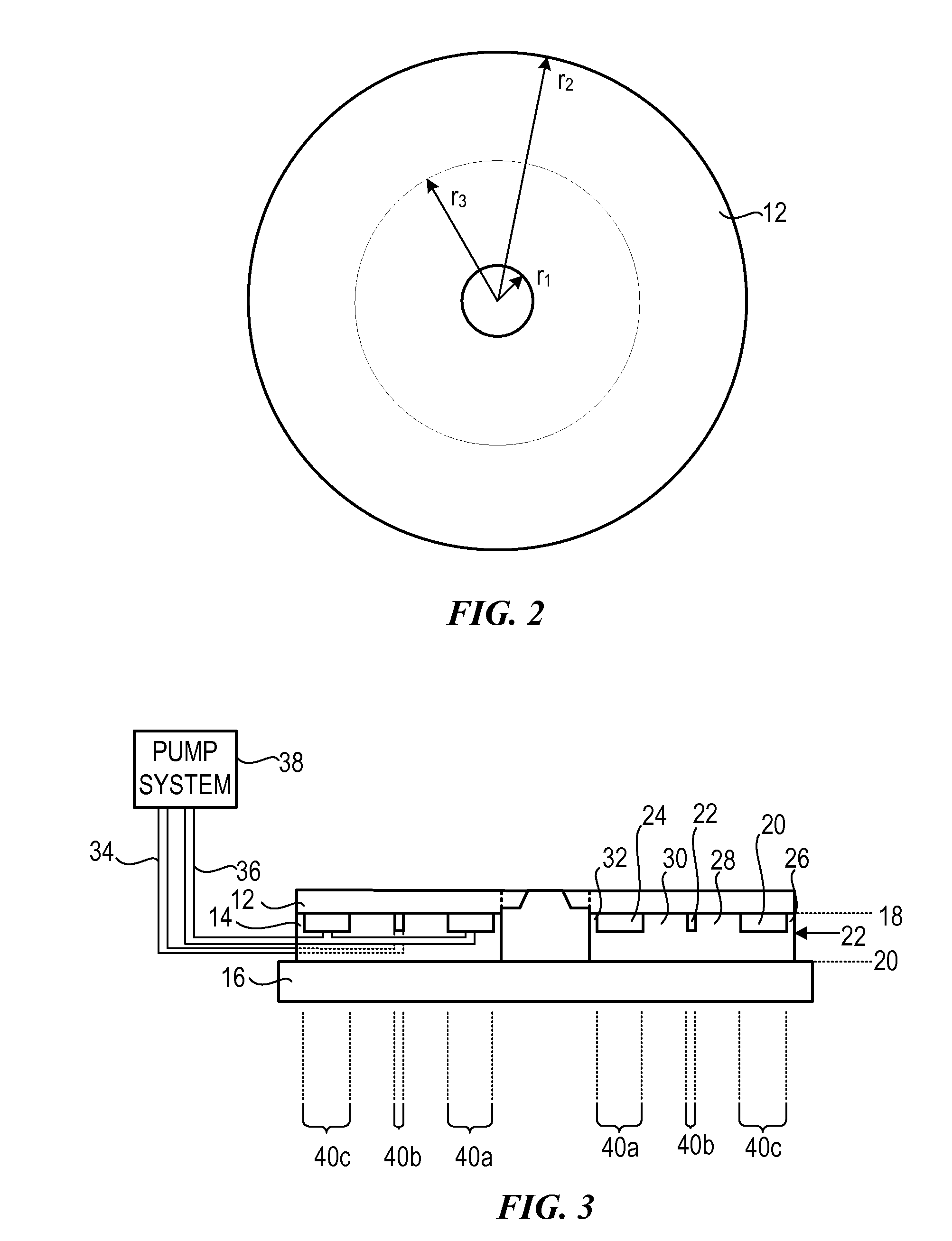
[0024] Referring to FIGS. 1 and 2, a system 10 to form a relief pattern on a substrate 12 is shown. Substrate 12 may have circular shape; however, in a further embodiment, substrate 12 may have any geometric shape. In the present example, substrate 12 may have a disk shape having an inner radius r1 and outer radius r2, with radius r2 being greater than radius r1. Further, defined between inner radius r1 and outer radius r2 is a middle radius r3, with middle radius r3 positioned substantially equidistant from inner radius r1 and outer radius r2.

[0025] Referring to FIG. 1, substrate 12 may be coupled to a substrate chuck 14. As shown substrate chuck 14 is a vacuum chuck, however, substrate chuck 14 may be any chuck including, but not limited to, vacuum, pin-type, groove-type, or electromagnetic, as described in U.S. Pat. No. 6,873,087 entitled “High-Precision Orientation Alignment and Gap Control Stages for Imprint Lithography Processes,” which is incorporated herein by reference. Su...


PUM

PropertyMeasurementUnit
Pressureaaaaaaaaaa
Volumeaaaaaaaaaa
Shapeaaaaaaaaaa

Abstract

The present invention is directed towards a method of expelling a gas positioned between a substrate and a mold, the substrate and the mold further having a liquid positioned therebetween.

Description

CROSS-REFERENCE TO RELATED APPLICATIONS [0001] The present application claims priority to U.S. Provisional Application No. 60 / 801,265, filed on May 18, 2006, entitled “Substrate Holding Apparatus and Methods for Data Storage Substrate” and U.S. Provisional Application No. 60 / 827,128, filed on Sep. 27, 2006, entitled “Double Side Imprinting”; and is a continuation-in-part of U.S. patent application Ser. No. 11 / 565,393, filed on Nov. 30, 2006, entitled “Method for Expelling Gas Positioned Between a Substrate and a Mold,” which claims priority to U.S. Provisional Application No. 60 / 748,380, filed on Dec. 8, 2005, entitled “Method and Apparatus for Imprinting with Preshaped Templates and / or Light Curable Liquids” and is a continuation of U.S. patent application Ser. No. 11 / 389,731, filed on Mar. 27, 2006, entitled “Imprint Lithography Substrate Processing Tool for Modulating Shapes of Substrates,” which is a continuation of U.S. patent application Ser. No. 10 / 293,224, now U.S. Pat. No. ...

Claims


Application Information

Patent Timeline
IPC IPC(8): B28B5/04
CPCB82Y10/00G03F7/0002B82Y40/00
Inventor CHOI, BYUNG-JINGANAPATHISUBRAMANIAN, MAHADEVANCHOI, YEONG-JUNMEISSL, MARIO J.
Owner CANON KK
Why Eureka
Try Eureka