Motor driving apparatus, motor driving method and disk driving apparatus

a technology of motor driving and disk driving, which is applied in the direction of motor/generator/converter stopper, electronic commutator, dynamo-electric converter control, etc., can solve the problems of increased cost, environmental resistance, motor remains stopped, and erroneous operation, and achieve reliable motor start

Active Publication Date: 2007-10-04
COLLABO INNOVATIONS INC
View PDF12 Cites 26 Cited by
  • Summary
  • Abstract
  • Description
  • Claims
  • Application Information

AI Technical Summary

Benefits of technology

[0024] According to the present invention, in a searching start mode as a mode at the start of the motor, a rotor position is determined on the basis of an actual neutral point as a neutral point of motor coils and a virtual neutral point to provide a voltage obtained by averaging motor terminal voltages, to provide an appropriate rotational speed (rotation start torque) at initial start. Since the neutral point difference voltage is not affected by a back electromotive voltage, it is possible by such provision of the neutral point difference voltage to detect rotor position information while being independent of the effe

Problems solved by technology

Meanwhile, a sensorless driving technique which requires no rotor position sensor is under development from the viewpoint of reliability, an increase in cost, and environmental resistance.
Therefore, when the initial position has not been successfully detected in the rotor position searching process, the m

Method used


Image

  • Motor driving apparatus, motor driving method and disk driving apparatus
  • Motor driving apparatus, motor driving method and disk driving apparatus
  • Motor driving apparatus, motor driving method and disk driving apparatus

Examples


embodiment 1

1. Configuration of Motor Driving Apparatus

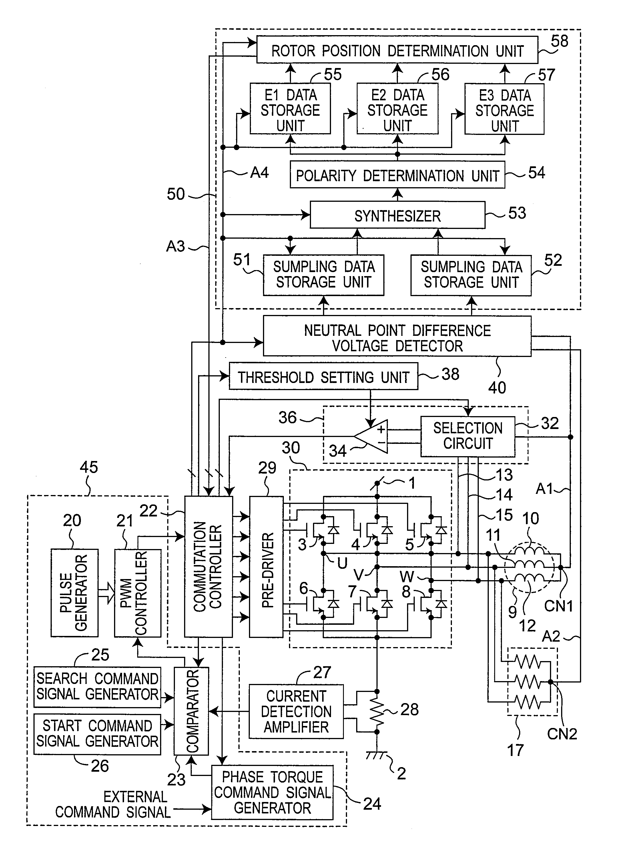
[0051]FIG. 1 shows a circuit configuration of a motor driving apparatus according to the present invention. The motor driving apparatus is a device for driving a motor 9.

[0052] The motor 9 includes a stator having coils 10 to 12 of three phases, a U-phase, a V-phase and a W-phase, and a rotor which is rotated by a rotating magnetic field generated in the stator. Although a three-phase motor is used as an example of the motor 9 in the present embodiment, an N-phase motor (N is an integer not smaller than 4) may be used. A U-phase coil 10, a V-phase coil 11 and a W-phase coil 12 have common connection at an actual neutral point CN1.

[0053] The motor driving apparatus supplies a drive power of the motor 9, and has an inverter circuit 30 including a plurality of switching elements 3 to 8, a pre-driver 29 for outputting a drive signal of each of the switching elements 3 to 8 in the inverter circuit 30, a commutation controller 22 for outputti...

embodiment 2

[0233] In Embodiment 1, the method for setting start conduction phases of the rotation start pulse is described by reference to FIG. 8. In the present embodiment, another example thereof is described.

[0234]FIG. 17A shows another example. In the example of FIG. 17A, polarity determination of E1, E2 and E3 are processed in an arithmetic circuit. Specifically, the polarities of E1, E2 and E3 are binarized. The binarized polarity values of E1, E2 and E3 are weighted and summed, and on the basis of the summed values, the start conduction phases of the rotation start pulse are set.

[0235] In the example of FIG. 17A, when the polarity of E1, E2 or E3 is positive, the polarity value is 1, and when the polarity is negative, the polarity value is 0. The weights to the polarity values of E1, E2 and E3 are 1, 2 and 4, respectively. Summed values for polarity determination are 4, 5, 1, 3, 2, and 6. In polarity determination, at he polarity values of E1, E2 and E3 are summed. When the summed val...

embodiment 3

[0239] A preferred mode of the rotor position search pulse is described. FIG. 18 shows characteristics of response signals of the neutral point difference voltage as the difference voltage between the actual neutral point CN1 and the virtual neutral point CN2, with respect to the rotor position on application of the rotor position search pulse with the two-phase conduction (from the U-phase coil terminal to the V-phase coil terminal). FIG. 18 shows a characteristic of two cases different in current level of the rotor position search pulse.

[0240] In FIG. 18, variations in neutral point difference voltage in the case where the rotor position search pulse current is relatively large is indicated by the solid line X. In FIG. 18, variations in neutral point difference voltage in the case where the rotor position search pulse current is relatively small is indicated by the broken line Y.

[0241]FIG. 18 shows that a sub-peak Ps and a sub bottom Bs in the case (solid line X) with the rotor ...


PUM


Abstract

A motor driving apparatus includes a neutral point difference voltage detecting unit operable to detect a difference voltage between a virtual neutral point of a resistor circuit connected in parallel to motor coils and an actual neutral point which is a common connection point of the motor coils, a rotor position detecting unit operable to detect a position of the rotor based on the difference voltage, and a controller operable to control commutation of an inverter. A rotation start torque applying process applies a rotation start pulse for providing rotation torque to the rotor based on a determined rotor position.

Description

BACKGROUND ART [0001] 1. Field of the Invention [0002] The present invention relates to a motor driving apparatus and a motor driving method which enable start of a motor without use of a sensor for detecting a rotor position. [0003] 2. Related Art [0004] In driving of a brushless motor, it is necessary to obtain an electrical relative position of a rotor to a stator in order to select an appropriate phase of the stator for supplying a current to apply a stable torque to the rotor. A variety of rotor position sensors are used for obtaining an electrical relative position of the rotor to the stator. Meanwhile, a sensorless driving technique which requires no rotor position sensor is under development from the viewpoint of reliability, an increase in cost, and environmental resistance. [0005] In such a sensorless driving technique, it is generally known that a rotor position is detected by reading a back electromotive voltage generated in the motor coil during rotation of the rotor. H...

Claims


Application Information

Patent Timeline
IPC IPC(8): H02P7/06H02P6/06H02P6/16H02P6/08H02P6/28
CPCH02P6/182G11B19/2054
Inventor FUKAMIZU, SHINGOYAMAMOTO, YASUNORIKUROSHIMA, SHINICHI
Owner COLLABO INNOVATIONS INC
Why Eureka
Try Eureka