Battery power detecting system and method

a battery power detection and power detection technology, applied in power supply testing, circuit monitoring/indication, transportation and packaging, etc., can solve the problems of vram losing data, data stored in vram losing, and vram still losing data

Inactive Publication Date: 2007-10-04
INVENTEC CORP
View PDF3 Cites 8 Cited by
  • Summary
  • Abstract
  • Description
  • Claims
  • Application Information

AI Technical Summary

Benefits of technology

[0008] In view of the above-mentioned problems of the prior art, it is a primary objective of the present invention to provide a battery power detecting system and method, both of which are applicable to an electronic device having a volatile random access memory (VRAM) for detecting the battery power of a backup battery of the VRAM, and generating alarm messages to notify a user of the electronic device to replace the backup battery with a new battery with sufficient battery power when the backup battery is determined to be lacking in battery power, so as to prevent data stored in the VRAM from being lost due to the lack of the battery power of the backup battery after the electronic device is powered-off.

Problems solved by technology

However, because the VRAM will lose data if supplied electrical power runs low, the electronic device is provided with a backup battery specified for the VRAM.
However, since the electronic device of the prior art is not provided with a battery power detecting mechanism, when the battery power provided by the backup battery of the VRAM is insufficient for the VRAM to hold data, and a user of the electronic device does not replace the backup battery with a new battery with sufficient power in time, the data stored in the VRAM will be lost due to the lack of battery power of the backup battery when the electronic device is powered-off.
However, such a battery power detecting mechanism of the prior art does not generate any alarm messages to notify the user to replace the backup battery with a new battery with sufficient battery power until the battery power of the backup battery is lower than a very small threshold power.
Consequently, the VRAM still loses its data.

Method used


Image

  • Battery power detecting system and method
  • Battery power detecting system and method
  • Battery power detecting system and method

Examples


Embodiment Construction

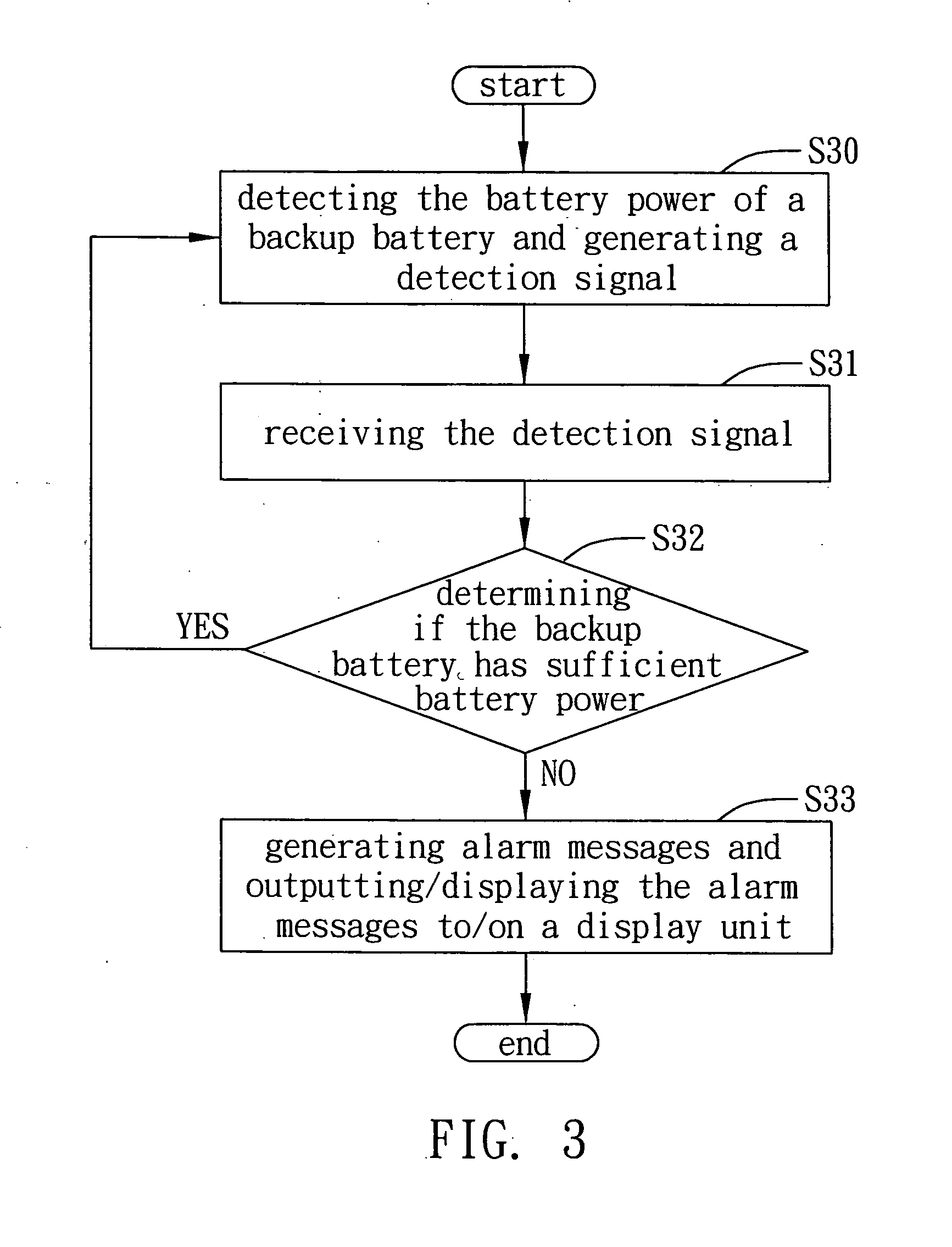
[0024] The following illustrative embodiments are provided to illustrate the disclosure of the present invention, these and other advantages and effects being readily understandable by those in the art after reading the disclosure of this specification. The present invention can also be performed or applied by other differing embodiments. The details of the specification may be changed on the basis of different points of view and applications, and numerous modifications and variations can be devised without departing from the spirit of the present invention.

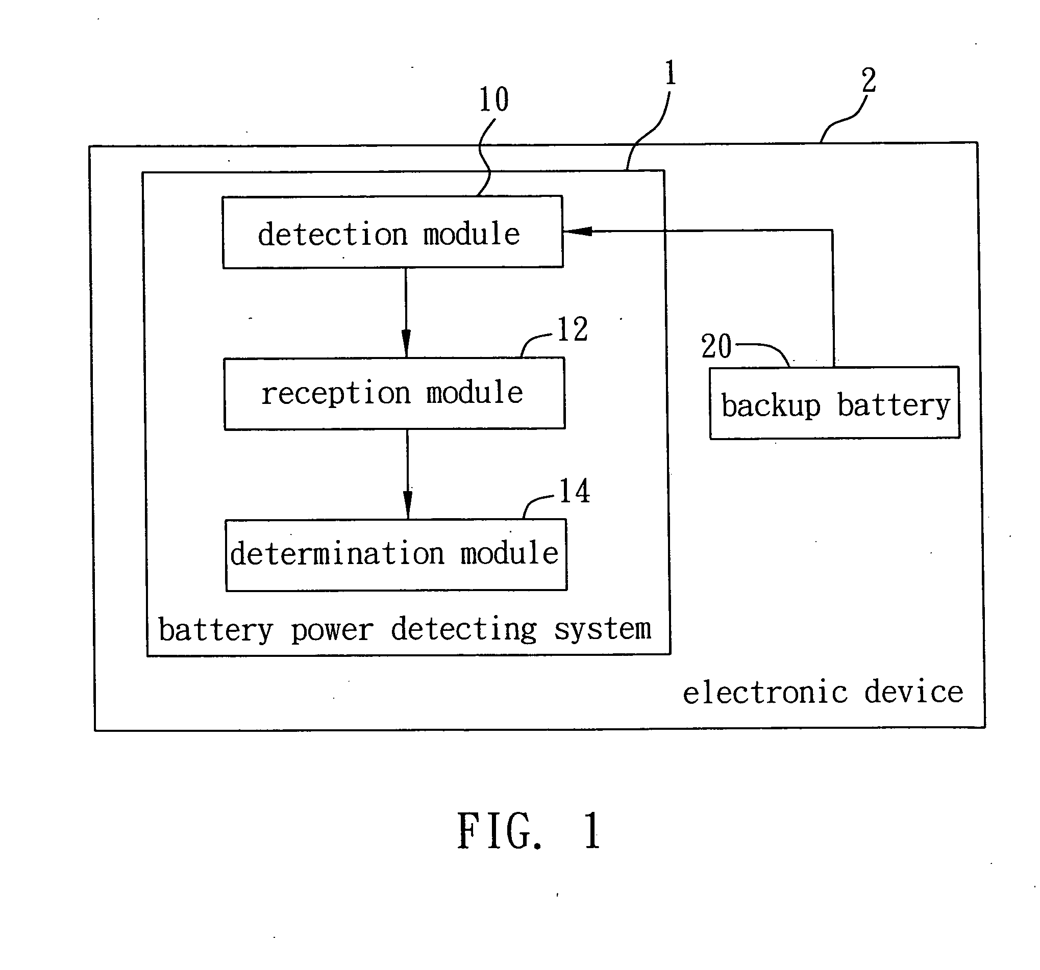
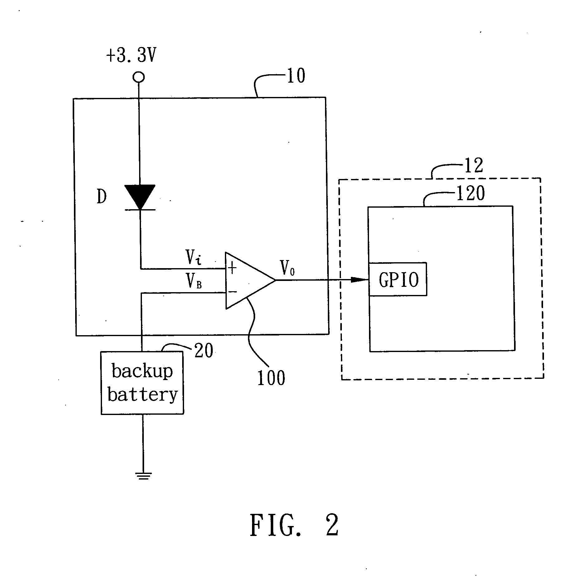
[0025]FIG. 1 is a functional block diagram of an electronic device 2 having a battery power detecting system 1 of the preferred embodiment according to the present invention. The battery power detecting system 1 is applicable in the electronic device 2 having a volatile random access memory (VRAM) and is used for detecting (or monitoring) battery power of a backup battery 20 of the VRAM. The VRAM, for example a CMOS memory, is u...


PUM


Abstract

A battery power detecting system is disclosed applicable to an electronic device having a volatile random access memory (VRAM) for detecting the battery power of a backup battery of the volatile random access memory. The battery power detecting system includes a detection module for detecting the battery power of the backup battery and for generating a detection signal; a reception module for receiving the detection signal; and a determination module for reading a state value of the detection signal received by the reception module, determining the battery power of the backup battery according to the state value, and generating alarm messages to notify a user that the backup battery is lacking in battery power when the backup battery is determined to be have insufficient battery power, so as to prevent data stored in the VRAM from being lost due to the lack of the battery power of the backup battery.

Description

BACKGROUND OF THE INVENTION [0001] 1. Field of the Invention [0002] The present invention relates to battery power detecting techniques; and, more particularly, to a battery power detecting system and method applicable to an electronic device having a volatile random access memory (VRAM) for detecting the backup battery power of the VRAM. [0003] 2. Description of Related Arts [0004] In general, an electronic computing device comprises a volatile random access memory (VRAM), which is used for storing a user's specified settings, such as the setup data of the basic input / output (BIOS) system of the device. However, because the VRAM will lose data if supplied electrical power runs low, the electronic device is provided with a backup battery specified for the VRAM. Therefore, even if the electronic device is powered-off, the VRAM can still maintain the data. [0005] Moreover, the VRAM has to have a working voltage approximately within 2.5-2.8V to reliably hold data. However, since the el...

Claims


Application Information

Patent Timeline
Patent Type & Authority Applications(United States)
IPC IPC(8): H02J7/00
CPCG01R31/40H02J2007/005H02J7/0047H02J7/0048
Inventor HUANG, KUN-HUNG
Owner INVENTEC CORP
Why Eureka
Try Eureka