Remote control signal transfer system

a remote control and signal technology, applied in the direction of electric controllers, instruments, ignition automatic control, etc., can solve the problems of ineffective remote control signals, interference between received remote control signals, and inability to reach the apparatus of infrared remote control signals, etc., and achieve excellent remote control signal transfer

Inactive Publication Date: 2007-10-04
SONY CORP
View PDF8 Cites 39 Cited by
  • Summary
  • Abstract
  • Description
  • Claims
  • Application Information

AI Technical Summary

Benefits of technology

[0012]An advantage of the present invention is to provide an excellent remote control signal transfer system that allows a remote control signal transmitted from a remote control to be appropriately transferred to a controlled apparatus installed at a separate place.
[0013]Another advantage of the present invention is to provide an excellent remote control signal transfer system that allows reception of remote control signals from a plurality of remote controls and transfer of the remote control signals to a plurality of controlled apparatuses.
[0014]Yet another advantage of the present invention is to provide an excellent remote control signal transfer system that implements, in a system including a plurality of remote controls and a plurality of controlled apparatuses, transfer of remote control signals from a single remote control to multiple controlled apparatuses (one-to-many transfer), from multiple remote controls to a single controlled apparatus (many-to-one transfer), and from multiple remote controls to multiple controlled apparatuses (many-to-many transfer).
[0015]Yet another advantage of the present invention is to provide an excellent remote control signal transfer system that makes it possible to pass remote control signals transmitted simultaneously at different places to a controlled apparatus while preventing the remote control signals from interfering with each other.
[0016]According to one embodiment of the present invention, there is provided a remote control signal transfer system for transferring a remote control signal sent by a remote control toward a controlled apparatus via a transmission medium, the system including one or more remote control signal reception devices each installed at a separate place from which a user remotely controls one or more controlled apparatuses. The system further includes one or more remote control signal reconstruction devices each installed for a separate one of the one or more controlled apparatuses. Each of the one or more remote control signal reception devices subjects a remote control signal obtained from a remote control receiving section to sampling, and transmits resultant data to the transmission medium to be eventually delivered to one or more of the one or more remote control signal reconstruction devices. Each of the one or more remote control signal reconstruction devices composes the remote control signals received from any one or more of the one or more remote control signal reception devices via the transmission medium into a single composed signal, and outputs the single composed signal to the corresponding controlled apparatus via a single remote control transmitting section.
[0017]Note that the term “system” in “remote control signal transfer system” as used herein refers to a logical collection of devices (or function modules that implement specific functions), and it does not manner whether all of the devices or function modules are contained in a single housing.

Problems solved by technology

There is a problem in that the infrared remote control signal does not reach an apparatus installed in a different room.
In the case where two or more infrared transmitters are pointed at a single controlled apparatus, if infrared receivers that are provided at two different positions receive remote control signals simultaneously, the received remote control signals may interfere with each other, making both the remote control signals ineffective.

Method used


Image

  • Remote control signal transfer system
  • Remote control signal transfer system
  • Remote control signal transfer system

Examples


first embodiment

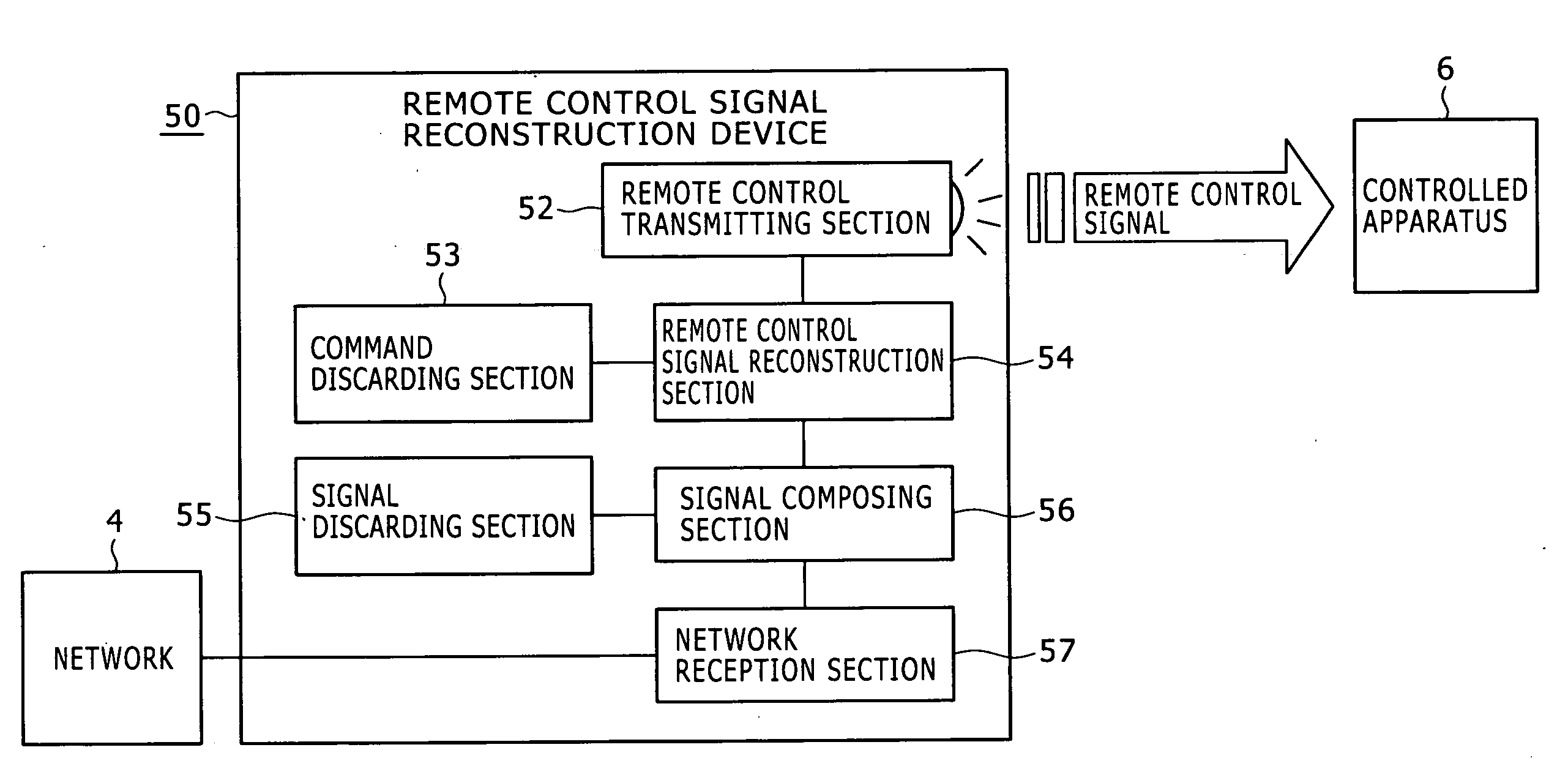
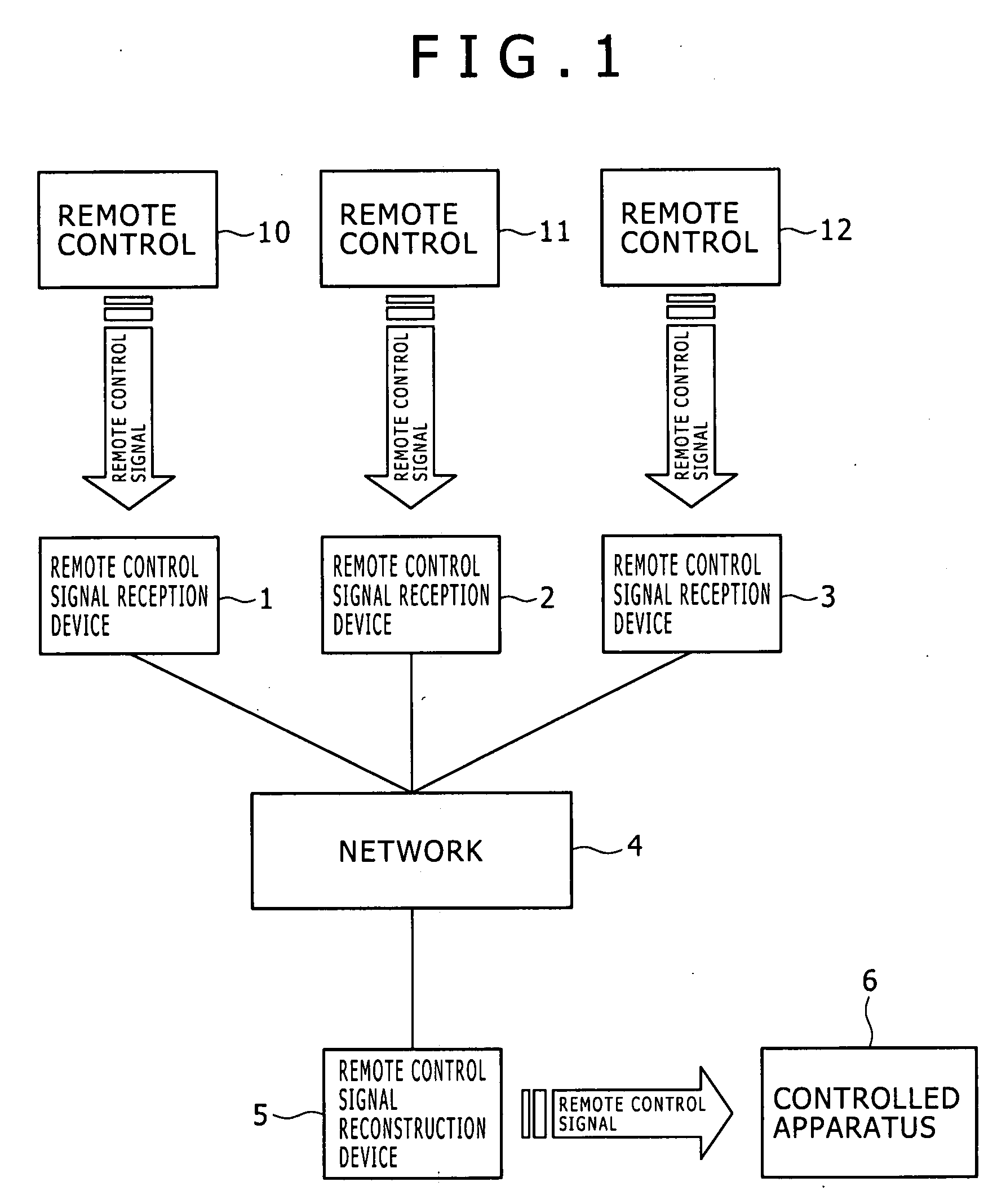
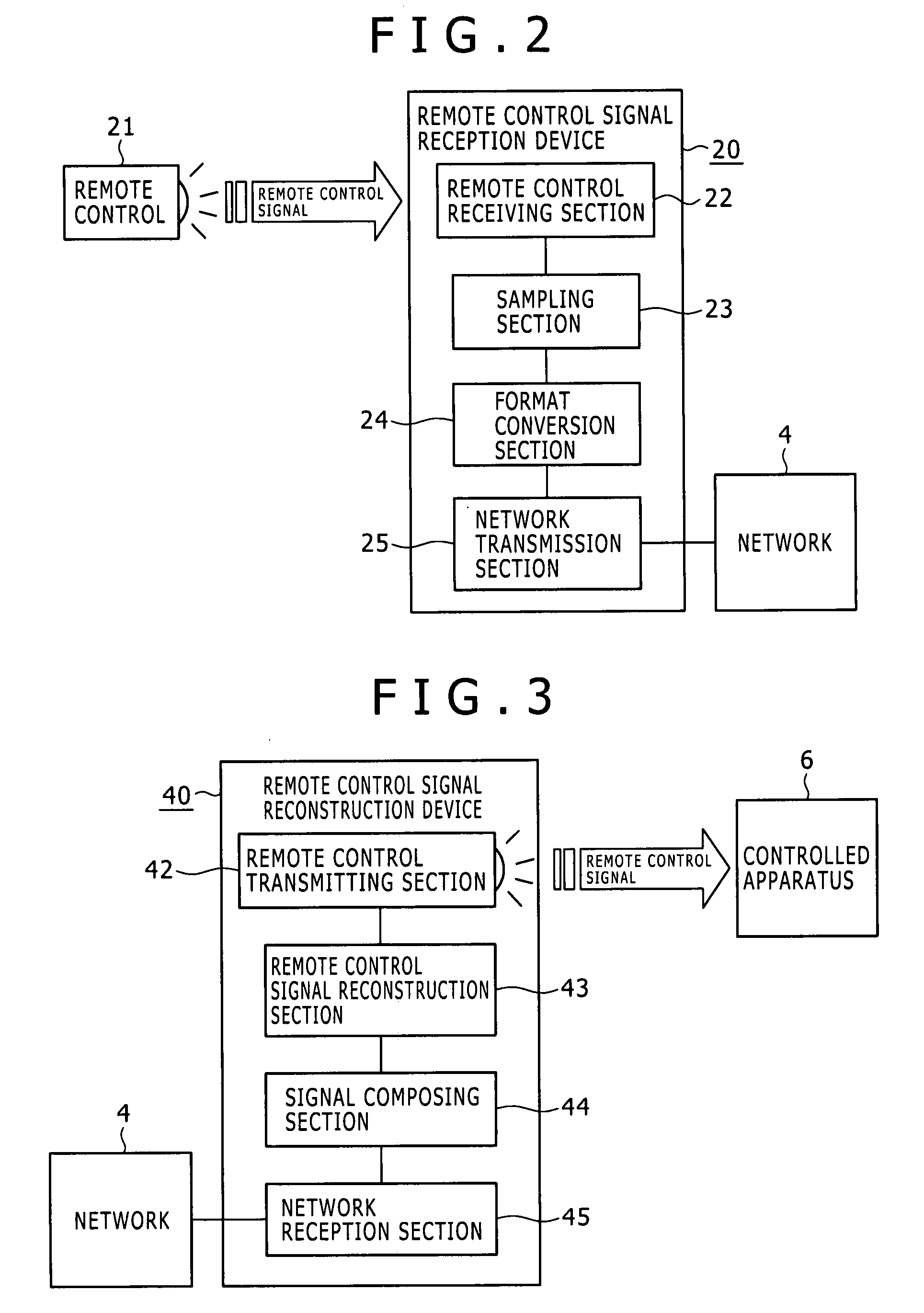
[0047]FIG. 1 is a schematic diagram illustrating an overall configuration of a remote control signal transfer system according to the present invention. This system includes multiple remote control signal reception devices and a single remote control signal reconstruction device, and transfer of remote control signals is performed in a many-to-one manner. In addition, as a method of transferring the remote control signals, a pass-through system is adopted. The pass-through system is a system in which a bit sequence, as it is, that is represented by a remote control signal received by the remote control signal reception device is transmitted as data to a network.

[0048]Remote controls 10 to 12 and a controlled apparatus (i.e., an apparatus to be controlled) 6 are located at a distance from one another. A remote control signal from any of the remote controls 10 to 12 may not reach the controlled apparatus 6 directly.

[0049]Relative positions of the remote control 10 and a remote control...

second embodiment

[0064]FIG. 6 illustrates a functional structure of a device 30 that operates as the remote control signal reception device in the remote control signal transfer system according to the In FIG. 6, the remote control signal reception device 30 includes a remote control receiving section 32, a sampling section 33, a command detection section 34, a command storage section 37, a format conversion section 35, and a network transmission section 36. The network transmission section 36 is connected to the network 4.

[0065]The remote control receiving section 32 converts the flashing on and off of light of a remote control signal transmitted from a remote control 31 into the On / Off of an electrical signal. The sampling section 33 takes samples of the On / Off of the electrical signal at a fixed frequency to store data of the samples temporarily. The command detection section 34 checks whether the thus stored data includes a pattern that corresponds to any command stored in the command storage s...

third embodiment

[0077]FIG. 11 is a schematic diagram illustrating an overall configuration of a remote control signal transfer system according to the present invention. The system of FIG. 11 includes a single remote control signal reception device and multiple remote control signal reconstruction devices, and the remote control signals are transferred from the single remote control signal reception device to the multiple remote control signal reconstruction devices (i.e., the transfer of the remote control signals is performed in a one-to-many manner). In addition, as the method of transferring the remote control signals, the pass-through system is adopted. The pass-through system is a system in which a bit sequence, as it is, that is represented by a remote control signal received by the remote control signal reception device is transmitted as data to a network.

[0078]A remote control 116 and controlled apparatuses 117 to 119 are located at a distance from one another, so that a remote control sig...


PUM


Abstract

A remote control signal transfer system for transferring a remote control signal sent by a remote control toward a controlled apparatus via a transmission medium, the system including: one or more remote control signal reception devices each installed at a separate place; and one or more remote control signal reconstruction devices each installed for a separate one of the one or more controlled apparatuses. Each remote control signal reception devices subjects a remote control signal obtained from a remote control receiving section to sampling, and transmits resultant data to the transmission medium. Each more remote control signal reconstruction devices composes the remote control signals received from any one or more of the remote control signal reception devices via the transmission medium into a single composed signal, and outputs the single composed signal to the corresponding controlled apparatus via a single remote control transmitting section.

Description

CROSS REFERENCES TO RELATED APPLICATIONS[0001]The present invention contains subject matter related to Japanese Patent Application JP 2006-075620, filed in the Japanese Patent Office on Mar. 17, 2006, the entire contents of which being incorporated herein by reference.BACKGROUND OF THE INVENTION[0002]1. Field of the Invention[0003]The present invention relates to a remote control signal transfer system for transferring a remote control signal transmitted by a remote control to an apparatus to be controlled at a separate place. In particular, the present invention relates to a remote control signal transfer system that involves reception of remote control signals from a plurality of remote controls and transfer of the remote control signals to a plurality of controlled apparatuses.[0004]More particularly, the present invention relates to a remote control signal transfer system for, in a system including a plurality of remote controls and a plurality of controlled apparatuses, transfe...

Claims


Application Information

Patent Timeline
Patent Type & Authority Applications(United States)
IPC IPC(8): G08C19/00
CPCG08C2201/40G08C23/04
Inventor MASATO, TSUYOSHISAKURAI, HISAO
Owner SONY CORP
Why Eureka
Try Eureka