Antenna configured for low frequency application

a low-frequency application, antenna technology, applied in the direction of resonant antennas, elongated active elements, protection material radiating elements, etc., can solve the problem of not being easily excited at such low-frequency frequencies

Active Publication Date: 2007-10-04
KYOCERA AVX COMPONENTS (SAN DIEGO) INC
View PDF6 Cites 22 Cited by
  • Summary
  • Abstract
  • Description
  • Claims
  • Application Information

AI Technical Summary

Benefits of technology

[0004] The present invention includes one or more embodiments of devices including an antenna equipped to support low frequency applications. In one embodiment, the device includes a conductive structure in an area that is intended to be in contact with the user of the device when the user is holding the device. The antenna is coupled to the conductive structure such that the conductive structure and user become part of the antenna element when the device is being used. The antenna element can be coupled to the conductive structure by a direct electrical connection. In one embodiment, a conductor connects the conductive structure of the device to the antenna element. The conductor can be configured in any of a number of forms, such as a conductive wire, conductive pads, etc. The user can be directly or indirectly coupled to the antenna through the conductive structure. For example, the user can directly contact the conductive structure or can be capacitively coupled to the conductive structure.

Problems solved by technology

One problem with existing mobile device antenna designs is that they are not easily excited at such low frequencies.

Method used


Image

  • Antenna configured for low frequency application
  • Antenna configured for low frequency application
  • Antenna configured for low frequency application

Examples


Embodiment Construction

[0045] In the following description, for purposes of explanation and not limitation, details and descriptions are set forth in order to provide a thorough understanding of the present invention. However, it will be apparent to those skilled in the art that the present invention may be practiced in other embodiments that depart from these details and descriptions.

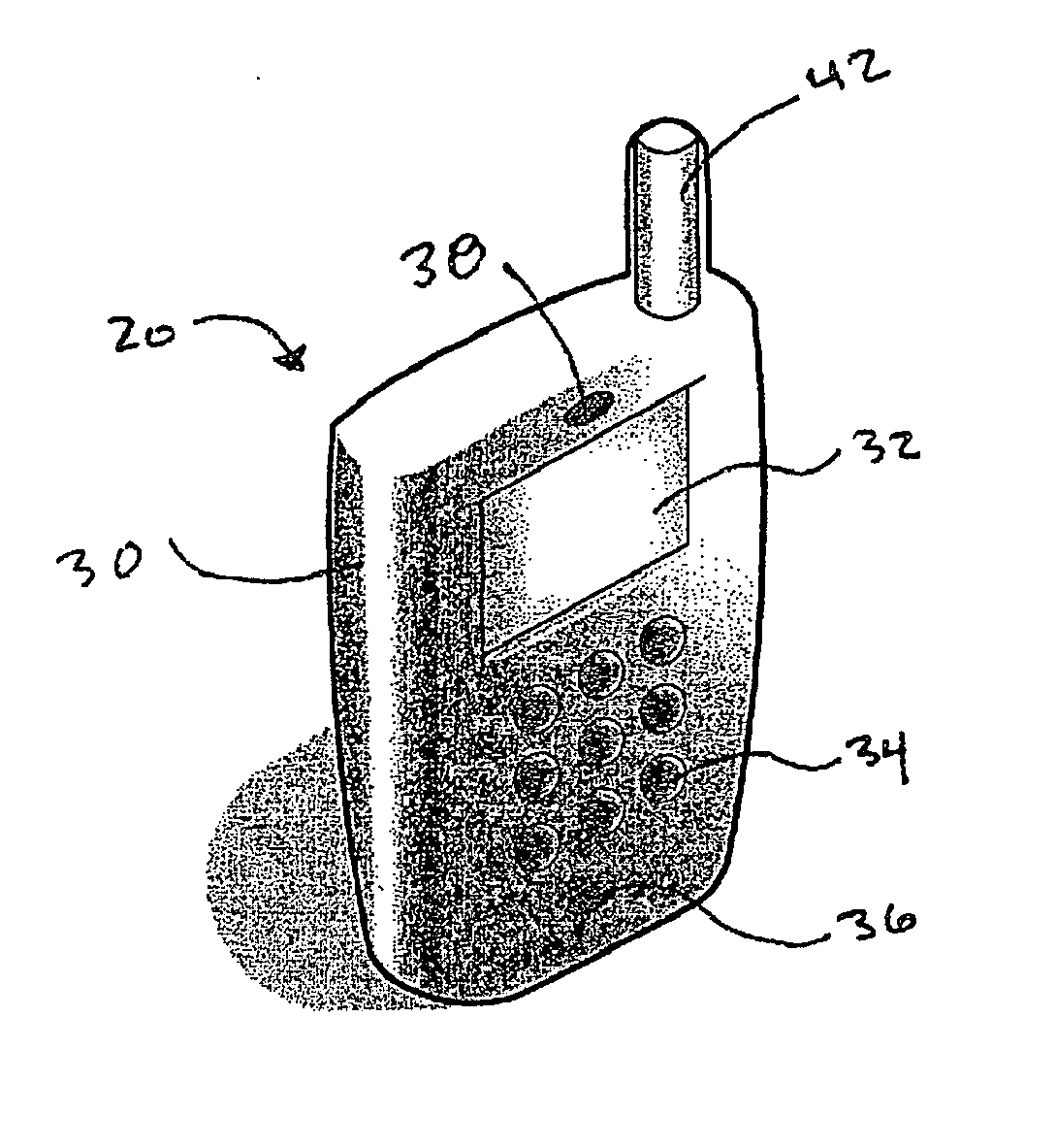
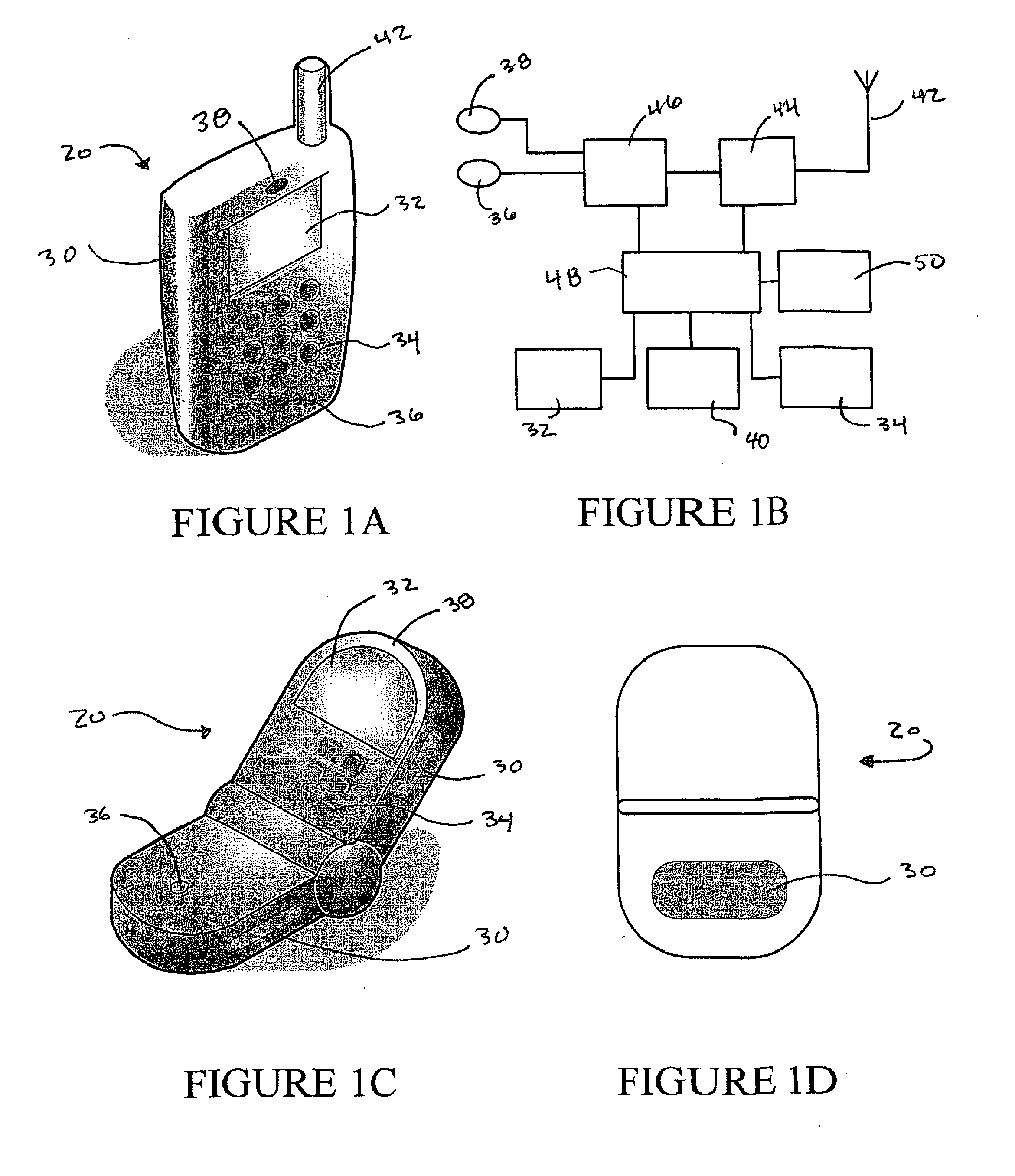
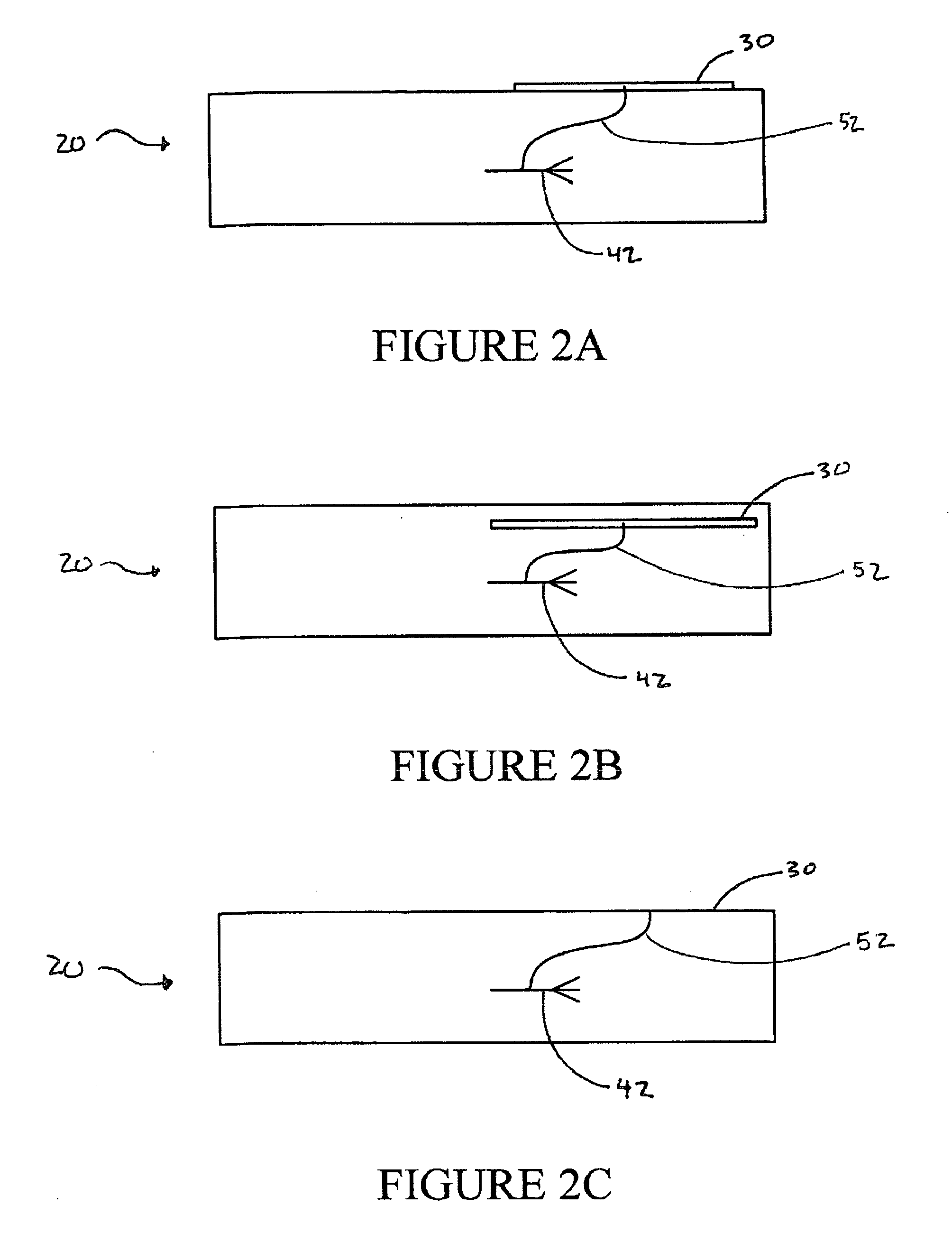
[0046] In the embodiments of the invention shown in FIGS. 1A-D, a mobile device (20), such as a mobile telephone, includes a conductive structure (30), a display (32) in the form of a liquid crystal display, a keypad (34), a microphone (36), an speaker (38), a battery (40), an antenna (42), radio interface circuitry (44), codec circuitry (46), a controller (48) and a memory (50). In the embodiment shown in FIGS. 1A and 2C, the conductive structure (30) comprises the device housing, which, in this example, comprises a conductive material, such as stainless steel. In this embodiment, a user of the mobile device (20) effective...


PUM


Abstract

An antenna configured for low frequency applications on a mobile device includes an antenna element coupled to a conductive structure which, in turn, is coupled to the user of the mobile device such that the user of the mobile device effectively becomes part of the antenna. The conductive structure can include, for example, the device housing being made from a conductive material, a conductive structure embedded inside the device housing, or conductive pads exposed in the device housing. The antenna element is electrically connected to the conductive structure and the user can be coupled to the conductive structure either through direct contact or through capacitive coupling.

Description

FIELD OF THE INVENTION [0001] The present invention relates generally to the field of wireless communications and devices, and more particularly to the design of antennas configured for low frequency applications. BACKGROUND [0002] As new generations of handsets and other wireless communication devices become smaller and embedded with more and more applications, new antenna designs will be needed to provide solutions to inherent limitations of these devices. With classical antenna structures, a certain physical volume is required to produce a resonant antenna structure at a particular radio frequency and with a particular bandwidth. In multi-band applications, more than one such resonant antenna structure may be required. With the advent of a new generation of wireless devices, such classical antenna structure will need to take into account beam switching, beam steering, space or polarization antenna diversity, impedance matching, frequency switching, mode switching, etc., in order ...

Claims


Application Information

Patent Timeline
Patent Type & Authority Applications(United States)
IPC IPC(8): H01Q1/24
CPCH01Q1/243H01Q9/42H01Q9/0442H01Q1/273
Inventor DESCLOS, LAURENTROWSON, SEBASTIANJONES, ROWLAND
Owner KYOCERA AVX COMPONENTS (SAN DIEGO) INC
Why Eureka
Try Eureka