Liquid crystal display, method for displaying color images, and method for controlling light sources of an LCD panel

a technology of liquid crystal display and color image, applied in the field of liquid crystal display (lcd), can solve the problems of increasing energy consumption, reducing the aperture ratio, and increasing the utility rate of light source and light efficiency, and not easy to adjust the mixed white light to become standard

Active Publication Date: 2007-10-04
AU OPTRONICS CORP
View PDF7 Cites 12 Cited by
  • Summary
  • Abstract
  • Description
  • Claims
  • Application Information

AI Technical Summary

Benefits of technology

[0010] This invention provides a liquid crystal display comprising a plurality of light sources of different colors and a control device. The control device controls the light sources of different colors to emit light in

Problems solved by technology

However, the arrangement of black matrixes will reduce the aperture ratio, the utility rate of the light source, and light efficiency, and increase the energy consumption.
When the white light, formed by red light,

Method used


Image

  • Liquid crystal display, method for displaying color images, and method for controlling light sources of an LCD panel
  • Liquid crystal display, method for displaying color images, and method for controlling light sources of an LCD panel
  • Liquid crystal display, method for displaying color images, and method for controlling light sources of an LCD panel

Examples


first embodiment

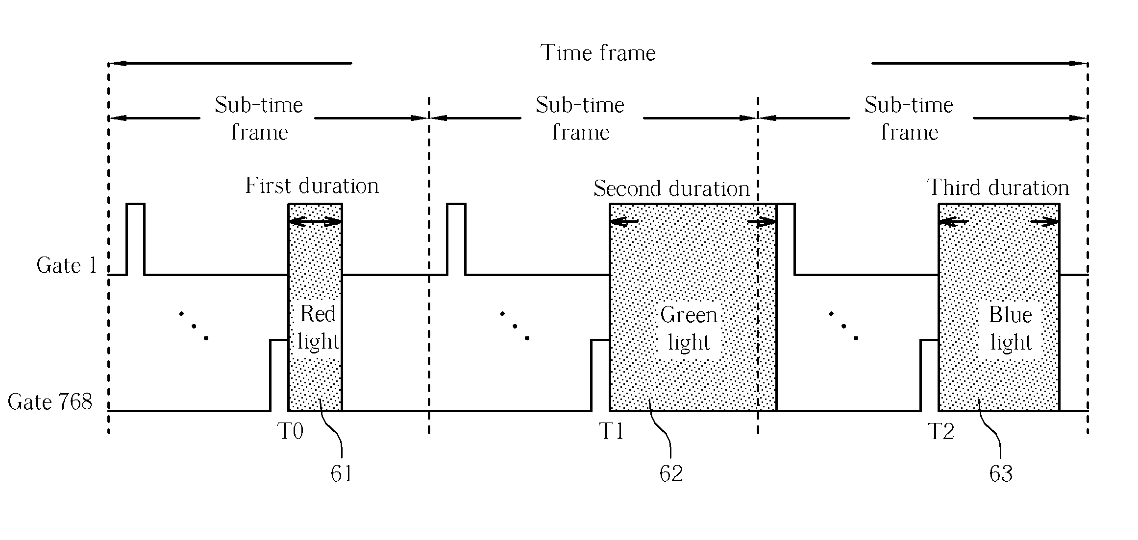
[0024]FIGS. 7-11 are timing charts showing light sources of different colors emitting in different duty cycles within different durations, controlled by the above-mentioned control device. FIG. 7 shows the first embodiment according to the present invention. As shown in FIG. 7, the time frame is divided into three sub-time frames for emitting light from the red light source 61, the green light source 62, and the blue light source 63, respectively.

[0025] For example, if the number of the pixels is 1280×768, at the beginning of the first sub-time frame, the liquid crystals of the 768 rows will receive a signal in sequence to determine the rotation of the corresponding liquid crystals of the red light based on the scan signal and the data signal. Then, the red light source 61 emits red light in the first duration. Next, at the beginning of the second sub-time frame, the liquid crystals of the 768 rows will receive a signal in sequence to determine the rotation of the corresponding liqu...

second embodiment

[0027]FIG. 8 is the second embodiment according to the present invention. As shown in FIG. 8, the first duration, the second duration, and the third duration are not all the same. In addition, the brightness (intensity) of the light sources can also be different. As shown in FIG. 8, the brightness of the green light source is the brightest, the brightness of the red light source is second, and the brightness of the blue light source is the darkest.

third embodiment

[0028]FIG. 9 shows the third embodiment according to the present invention. As shown in FIG. 9, the first duration, the second duration, and the third duration are not all the same. In addition, the beginning of each duration follows the input period for inputting the signal to determine the rotation of the corresponding liquid crystal and the rotating period (response time) of the liquid crystal (Tlc). Also, the brightness of the light sources of different colors can be different.


PUM


Abstract

A liquid crystal display includes a plurality of light sources of different colors and a control device. The control device is used to control the light sources to emit light with different duty cycles. Through persistence of vision, light generated by the light sources will form an image of desired colors. White balance can be achieved by controlling the duty cycles.

Description

BACKGROUND OF THE INVENTION [0001] 1. Field of the Invention [0002] The present invention relates to a liquid crystal display (LCD) and related methods for operations of displays, and more particularly, to an LCD having a plurality light sources of different colors sequentially emitting light within different duty cycles and related methods for operations of displays. [0003] 2. Description of the Prior Art [0004] Since a liquid crystal display (LCD) has the advantage of low operating voltage and low power consumption, it has a great potential to replace the conventional, cumbersome cathode ray tube terminal (CRT). [0005] Refer to FIGS. 1 and 2. FIG. 1 is a schematic diagram of an LCD panel 2 of the prior art, and FIG. 2 is a schematic diagram of a back light source 3 and a pixel 20 of the LCD panel 2. The conventional liquid crystal display comprises an LCD panel 2, and a back light source 3. The LCD panel 2 has a plurality of pixels 20, each constituted by red, green, and blue sub-...

Claims


Application Information

Patent Timeline
IPC IPC(8): G09G3/36
CPCG09G3/3413G09G2310/0235G09G2320/0666G09G2320/064G09G2320/0633
Inventor LIU, CHUN-TINGWANG, CHIH-WEIWEY, CHIN-DERYU, YA-YUN
Owner AU OPTRONICS CORP
Why Eureka
Try Eureka