Apparatus and method for converting interlaced image into progressive image

Inactive Publication Date: 2007-10-04
SAMSUNG ELECTRONICS CO LTD
View PDF36 Cites 15 Cited by
  • Summary
  • Abstract
  • Description
  • Claims
  • Application Information

AI Technical Summary

Benefits of technology

[0012] According to an aspect of the present invention, there is provided an apparatus and method for converting an interlaced image into a progressive image, in which image conversion is performed considering characteristics of a region and the orientation of an edge

Problems solved by technology

However, when an interlaced image with much motion is converted into a progressive image using the blend method, a blur and an afterimage are likely to occur, and diagonal aliasing may occur at an edge of the image.
However, the edge dependent interpolation method is disadvantageous in that the edge orientation in an image is likely to be erroneously determined and use of only one field of an interlaced image during interpolation may cause a large difference between chromaticity values of the interlaced image and a progressive image.
Also, color blurring may occur during conversion of an imag

Method used


Image

  • Apparatus and method for converting interlaced image into progressive image
  • Apparatus and method for converting interlaced image into progressive image
  • Apparatus and method for converting interlaced image into progressive image

Examples


Example

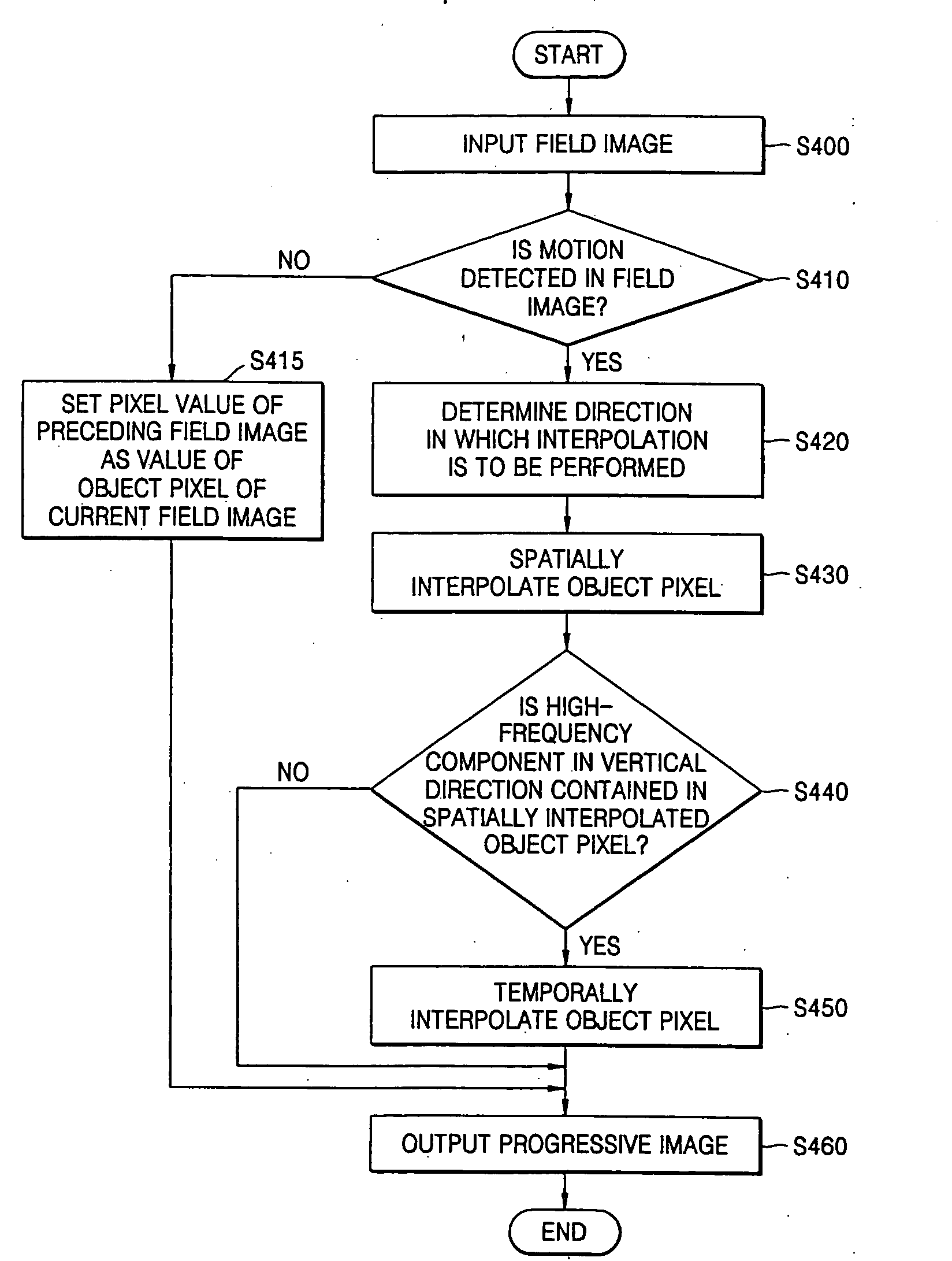
[0038] Reference will now be made in detail to the embodiments of the present invention, examples of which are illustrated in the accompanying drawings, wherein like reference numerals refer to the like elements throughout. The embodiments are described below to explain the present invention by referring to the figures.

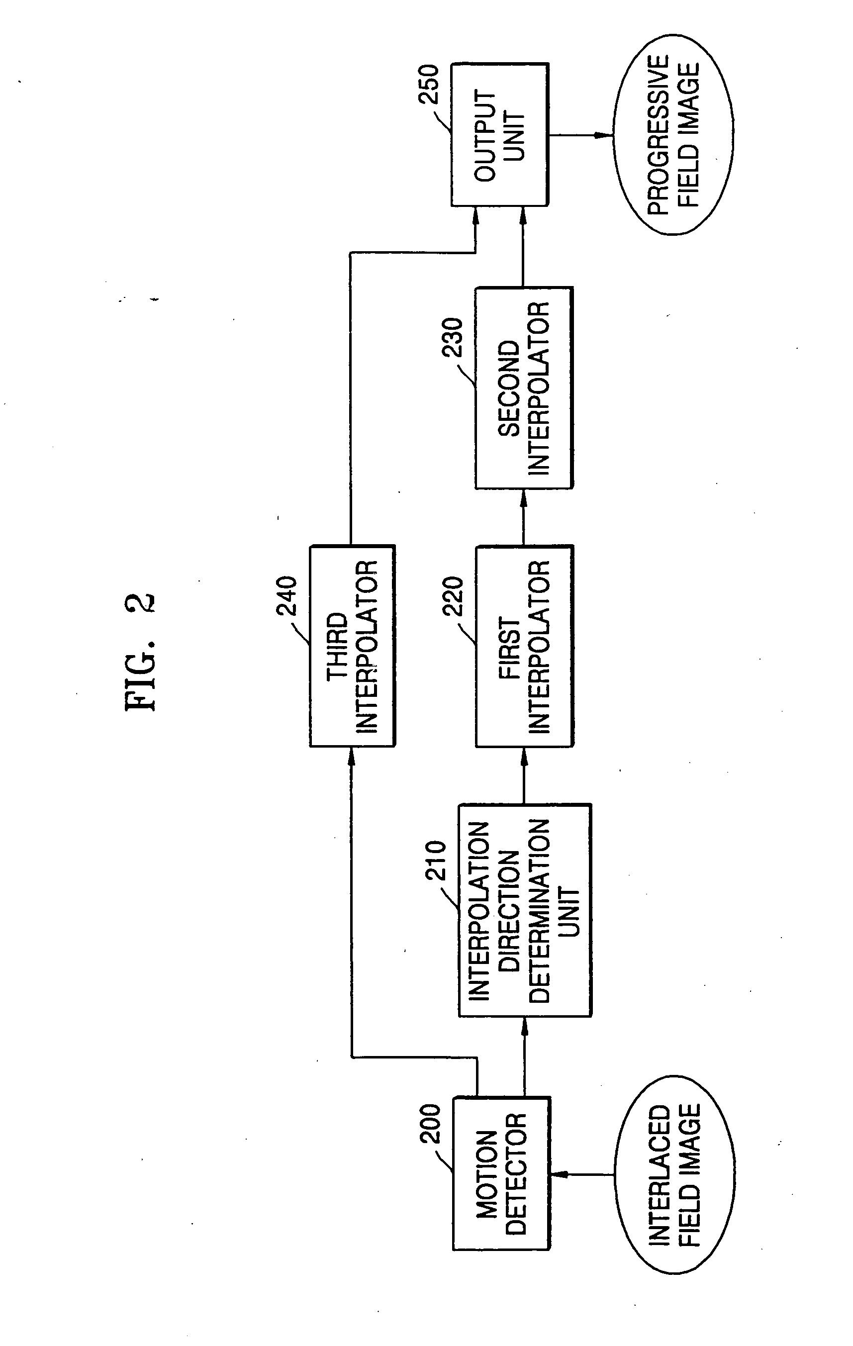
[0039]FIG. 2 is a block diagram of an apparatus for converting an interlaced image into a progressive image according to an embodiment of the present invention. The apparatus includes motion detector 200, an interpolation direction determination unit 210, a first interpolator 220, a second interpolator 230, a third interpolator 240, and an output unit 250.

[0040]FIG. 3 is a detailed block diagram of the interpolation direction determination unit 210 of FIG. 2. Referring to FIG. 3, the interpolation direction determination unit 210 includes a vertical differential value calculator 310, a first differential value calculator 320, a second differential value calculator 3...


PUM


Abstract

An apparatus and method for converting an interlaced image into a progressive image, the apparatus includes a motion detector which detects motion at an object pixel of the interlaced field image, using proceeding and following field images; an interpolation direction determination unit which determines a direction in which the object pixel is to be interpolated, using values of pixels along scan lines where the object pixel is not located when motion at the object pixel is detected; a first interpolator which spatially interpolates the object pixel according to the determined direction; and a second interpolator which resets a value of the object pixel using corresponding values of pixels of the preceding and following field images and a value obtained by spatially interpolating the object pixel when the object pixel contains high-frequency components in the vertical direction.

Description

CROSS-REFERENCE TO RELATED APPLICATION [0001] This application claims the priority of U.S. Provisional Patent Application No. 60 / 604,463, filed on Aug. 26, 2004 in the United States Patent and Trademark Office, the disclosure of which is incorporated herein by reference.BACKGROUND OF THE INVENTION [0002] 1. Field of the Invention [0003] The present invention relates to an apparatus and method for converting an interlaced image into a progressive image, and more particularly, to an apparatus and method for converting an interlaced image into a progressive image by interpolating the interlaced image considering characteristics of a region and the orientation of an edge to which a pixel to be interpolated belongs. [0004] 2. Description of the Related Art [0005] There are various methods of converting an interlaced image into a progressive image. In particular, a blend method and an edge dependent interpolation method are mainly used. [0006] In the blend method, interpolation is perform...

Claims


Application Information

Patent Timeline
IPC IPC(8): G09G5/00H04N5/44
CPCH04N5/144H04N7/0135H04N7/012
Inventor KIM, HYE YUNKIM, HYUN MUN
Owner SAMSUNG ELECTRONICS CO LTD
Why Eureka
Try Eureka