Fire Detector Device
a detector device and detector technology, applied in the field of fire detector devices, can solve the problems of insufficient sensitivity of small and very small particles, inability to meet the actual conditions of fire recognition, and difficulty in recognizing open fires in due tim
- Summary
- Abstract
- Description
- Claims
- Application Information
AI Technical Summary
Benefits of technology
Problems solved by technology
Method used
Image
Examples
second embodiment
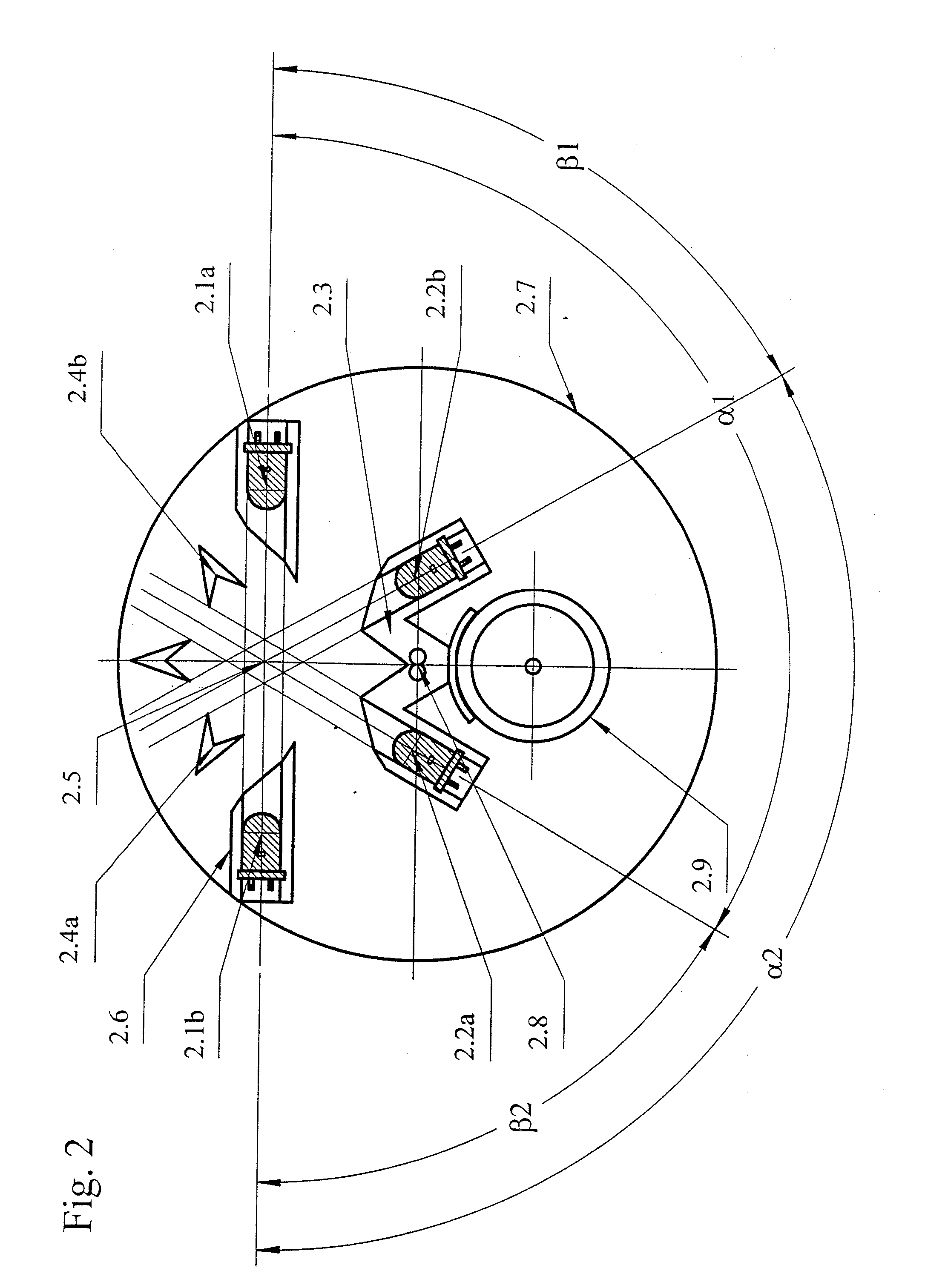
[0031]FIG. 2 shows the detector with the same components as in FIG. 1, but with a different geometrical arrangement. In order to explain this arrangement in closer detail, the first digit of the respective reference numeral is provided here with “2” instead of “1”. In contrast to FIG. 1, only the radiation axes of the infrared-radiating LED 2.1a and the blue-radiating LED 2.1b which go through the measuring center 2.5 will coincide. The receiving axis of the photodiode 2.2a encloses an angle α1=120° with the radiation axis of LED 2.1a and with the radiation axis of the blue-radiating LED 2.1b an angle β2=600. The receiving axis of the photodiode 2.2b encloses conversely with the radiation axis of the infrared-radiating LED 2.1a an angle α1=60° and with the radiation axis of the blue-radiating LED 2.1b an angle α2=120°. Accordingly, the first photodiode 2.2a measures the forward scattered radiation of the “infrared” LED 2.1a and the backward scattered radiation of the “blue” LED 2.1b...
first embodiment
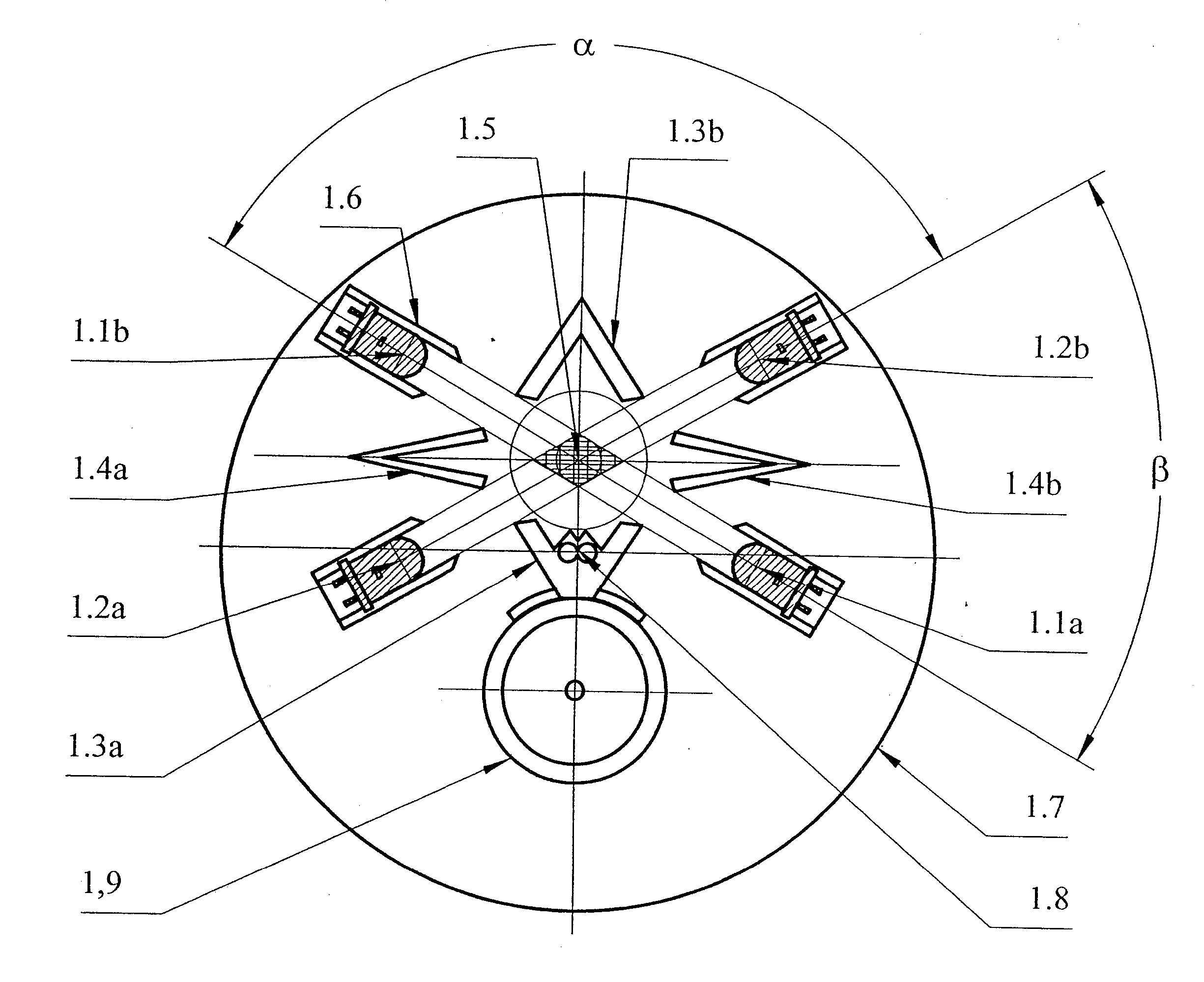
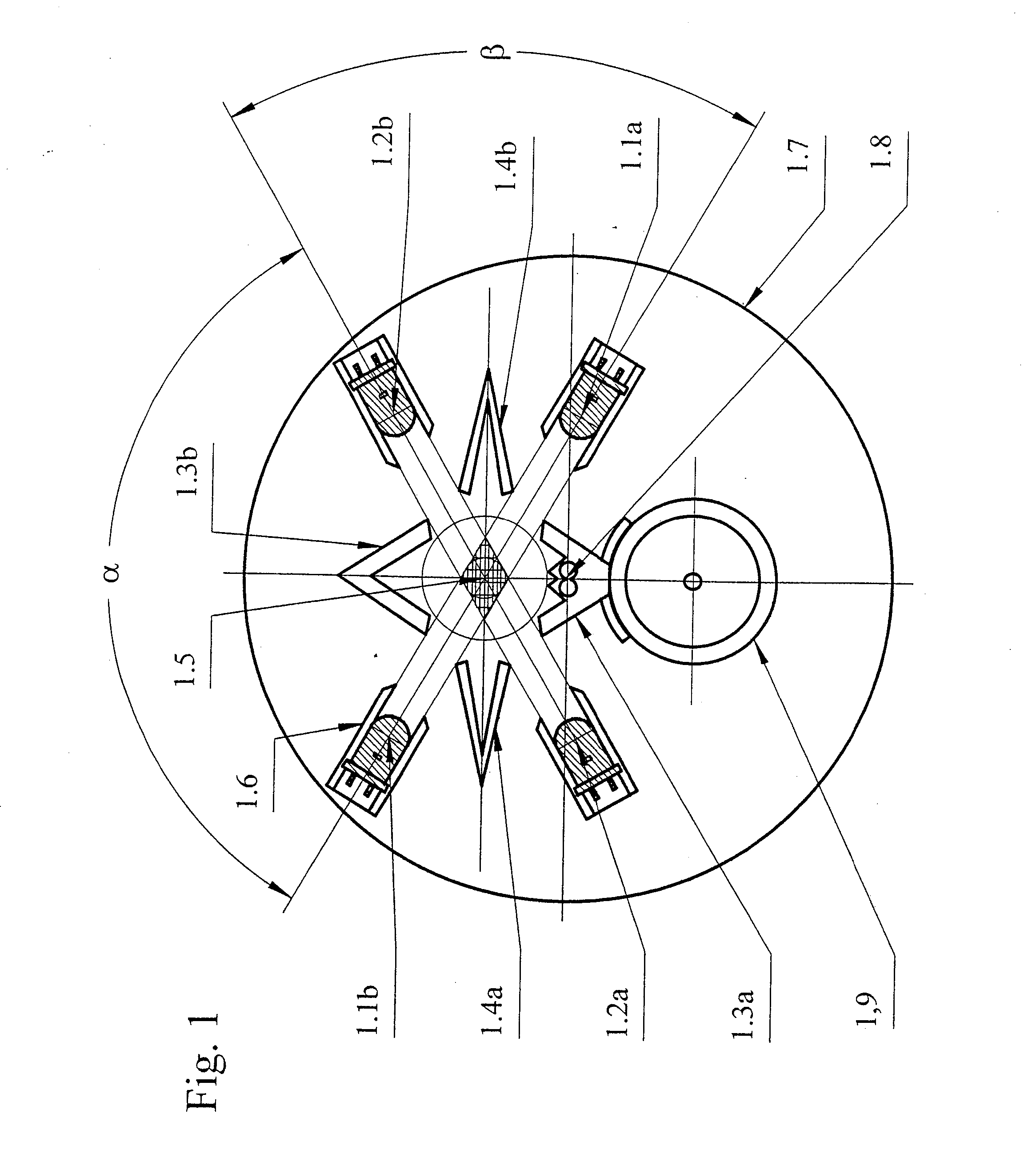
[0032] The photodiodes 2.2a and 2.2b can exchange their positions with the LEDs 2.1a and 2.1b, so that the two photodiodes are situated precisely opposite with respect to the measuring center 2.5. This geometrical arrangement of the four components, i.e., that of the two LEDs and the two photodiodes, is less favorable than that of FIG. 1 because only 75% of the four measured scattered radiations originate from the same measuring volume. This is illustrated by the intersecting surfaces between the beams which are shown by omitting the angular dependency both of the intensity of the emitted radiations as well as the sensitivity of the photodiodes as well as the diffraction effects which occur unavoidably on the edges. In the case of detectors which (as in the embodiment) comprise further sensors such as 2.8 and 2.9, there is an additional factor that the measuring center 2.5 is disposed in a strongly eccentric fashion with respect to the center of the base plate 2.7. This leads to the...
third embodiment
[0033]FIG. 3 shows the detector with the same components as in FIG. 2, but with a different geometrical arrangement. In order to illustrate this in closer detail, the first digit of the respective reference numeral is provided here with “3” instead of “2”. In contrast to FIG. 1, only the receiving axes of the photodiodes 3.2a and 3.2b coincide which pass through the measuring center 3.5. These receiving axes form the main axis. The “infrared” LED 3.1a encloses with the latter an acute angle α1=60° and an obtuse angle β1=120°. The “blue” LED 3.1b is situated opposite of the “infrared” LED 3.1a with respect to the main axis, which “blue” LED accordingly encloses with the main axis an acute angle β2=600 and an obtuse angle α2=120°. As a result, the photodiode 3.2a receives both the infrared forward scattered radiation as well as the blue forward scattered radiation, whereas the photodiode 3.2b receives both the infrared backward scattered radiation as well as the blue backward scattere...
PUM
| Property | Measurement | Unit |
|---|---|---|
| acute angle | aaaaa | aaaaa |
| angle | aaaaa | aaaaa |
| angle | aaaaa | aaaaa |
Abstract
Description
Claims
Application Information
 - R&D
- Intellectual Property
- Life Sciences
- Materials
- Tech Scout
- Unparalleled Data Quality
- Higher Quality Content
- 60% Fewer Hallucinations
Browse by: Latest US Patents, China's latest patents, Technical Efficacy Thesaurus, Application Domain, Technology Topic, Popular Technical Reports.
© 2025 PatSnap. All rights reserved.Legal|Privacy policy|Modern Slavery Act Transparency Statement|Sitemap|About US| Contact US: help@patsnap.com


