Zoom lens and projection display device using the same

a technology of zoom lens and projection display device, which is applied in the field of image forming zoom lens, can solve the problems of lack of brightness, lack of improvement in distortion correction, etc., and achieve the effect of reducing weight, improving weather resistance, and satisfactorily adjusting

Inactive Publication Date: 2007-10-04
FUJI PHOTO OPTICAL CO LTD
View PDF3 Cites 18 Cited by
  • Summary
  • Abstract
  • Description
  • Claims
  • Application Information

AI Technical Summary

Benefits of technology

[0018]According to the configuration set forth above, such a zoom lens of the five lens groups can be obtained that the zoom lens is bright and has a wide angle of view and that the first lens group has the negative refractive power. Also, the first lens group having the negative refractive power includes the two negative meniscus lenses whose convex surfaces are directed to the magnification side, respectively. The glass and the plastic are selected as the material of the lenses of the first lens group sequentially from the magnification side. Since the two lenses are formed respectively to have the negative meniscus shape and have convex surfaces directed to the magnification side, the convex lens surface on the reduction side gets into the concave lens surface on the magnification side. Such a configuration is advantageous to a size reduction in both the lens diameter direction and the lens length direction. In addition, since the negative meniscus lens made of glass satisfies the conditional expressions (1) and (2), a weight reduction can be attained and various aberrations, especially the lateral color, can be corrected satisfactorily. Also, since the glass is selected as the material of the lens located on the outermost side and exposed to the external environment, the weather resistance can be improved. Also, since the negative meniscus lens made of plastic is effective in reducing a weight and a cost, the satisfactory distortion correction can be accomplished when this lens is used as the second lens that is not exposed to the external environment and also this lens has an aspheric surface.
[0019]The zoom lens of the invention is configured as a five-group-configuration having the first lens group set forth above. Therefore, improvement in a weight reduction, a size reduction, brightness and a wider angle of view can be achieved. Various aberrations can be corrected satisfactorily. Furthermore, the excellent weather resistance can be achieved.

Problems solved by technology

However, the zoom lens disclosed in JP 2002-148516 A still leaves room for improvement as to a distortion correction and has not a sufficient brightness.

Method used


Image

  • Zoom lens and projection display device using the same
  • Zoom lens and projection display device using the same
  • Zoom lens and projection display device using the same

Examples


example 1

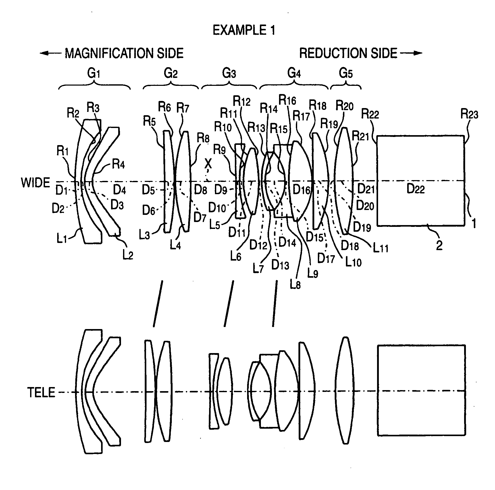
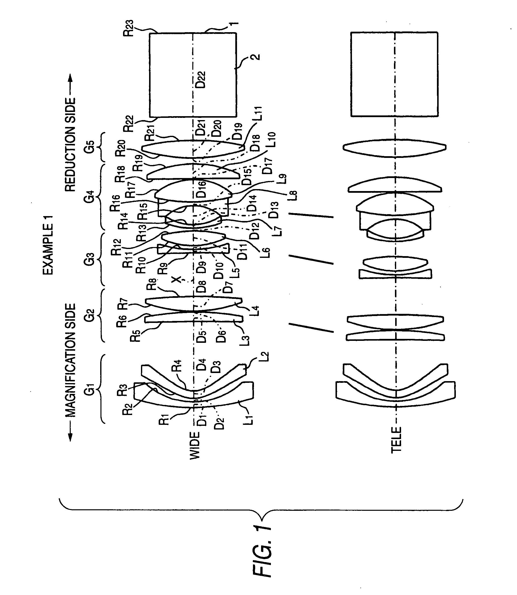
[0061]The zoom lens according to this example 1 is configured as shown in FIG. 1, as described above. More particularly, this zoom lens is configured sequentially from the magnification side in such a way that the first lens group G1 includes the first lens L1 made of the negative meniscus lens whose convex surface is directed to the magnification side and the second lens L2 made of the negative meniscus lens whose convex surface is directed to the magnification side; the second lens group G2 includes the third lens L3 made of the positive meniscus lens whose convex surface is directed to the reduction side and the fourth lens L4 made of a biconvex lens; the third lens group G3 includes the fifth lens L5 made of a biconcave lens and the sixth lens L6 made of a biconvex lens; the fourth lens group G4 includes the cemented lens constructed formed by joining the seventh lens L7 made of the negative meniscus lens whose convex surface is directed to the magnification side, the eighth len...

example 2

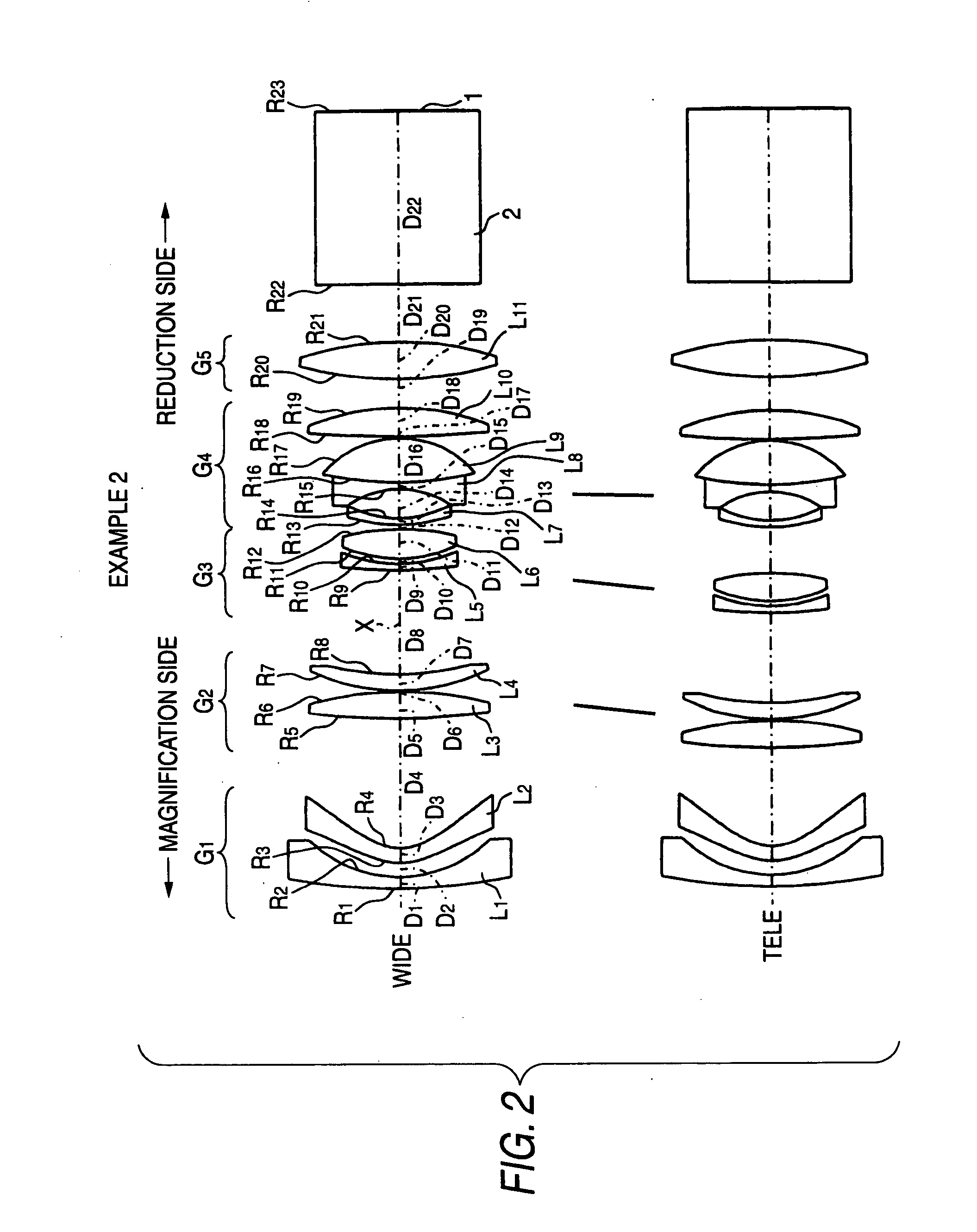
[0068]FIG. 2 shows a schematic configuration of a zoom lens according to an example 2. The zoom lens of the example 2 is configured substantially similarly to that of the example 1. A major difference from the example 1 is that the third lens L3 is made of a biconvex lens, that the fourth lens L4 is made of a positive meniscus lens whose convex surface is directed to the magnification side, that the fifth lens L5 is made of a negative meniscus lens whose convex surface is directed to the magnification side, and that the tenth lens L10 is made of a biconvex lens.

[0069]In this example 2, radii R of curvature of the respective lens surfaces, center thicknesses of the respective lenses and air distances D between the respective lens, refractive indices Nd of the respective lenses with respect to d-line and Abbe numbers νd of the respective lenses with respective to d-line are given on the upper portion of a table 3.

[0070]Also, the distance D4 between the first lens group G1 and the seco...

example 3

[0075]FIG. 3 shows a schematic configuration of a zoom lens according to an example 3. The zoom lens according to the example 3 is configured substantially similarly to that according to the example 1, but is different from the example 1 mainly in that the fourth lens group G4 includes three lenses and the fifth lens group G5 includes two lenses. More particularly, this zoom lens is configured sequentially from the magnification side in such a way that the first lens group G1 includes the first lens L1 made of a negative meniscus lens whose convex surface is directed to the magnification side and the second lens L2 made of a negative meniscus lens whose convex surface is directed to the magnification side; the second lens group G2 includes the third lens L3 made of a biconvex lens and the fourth lens L4 made of a biconvex lens; the third lens group G3 includes the fifth lens L5 made of a biconcave lens and the sixth lens L6 made of a biconvex lens; the fourth lens group G4 includes ...


PUM


Abstract

A zoom lens includes in order from a magnification side a first to fifth lens groups G1 to G5. The first and fifth lens group is fixed during varying of a power. The first lens group executes focusing. The second, third and fourth lens groups move interrelatedly during the varying of the power. The first lens group includes in order from the magnification side a glass lens having a convex surface of a negative meniscus shape directed toward the magnification side, and a plastic lens having a convex surface of a negative meniscus plane directed toward the magnification side. At least one surface of the plastic lens is an aspheric surface. The glass lens satisfies:
1.56<Nd<1.80
νd>45
where Nd denotes refractive index with respect to d-line, and νd denotes Abbe number with respect to d-line.

Description

BACKGROUND OF THE INVENTION[0001]1. Technical Field[0002]The invention relates to an image forming zoom lens for use in an imaging device, such as CCD and a camera tube, or in a camera using a silver halide film; and relates to a projection zoom lens for use in a projection television and. More particularly, the invention relates to a projection zoom lens for use in a projection display device using a liquid crystal display device or DMD (digital micromirror device), and a projection display device using the same.[0003]2. Description of the Related Art[0004]JP 2002-148516 A (corresponding to U.S. Pat. No. 6,542,311) discloses a zoom lens having the five-group configuration. This zoom lens has a power arrangement of negative, positive, positive, negative and positive sequentially from the magnification side. Although JP 2002-148516 A uses only glass spherical lenses but uses no aspherical lens, JP 2002-148156 A achieves miniaturization. Also, this zoom lens is configured so that a te...

Claims


Application Information

Patent Timeline
Patent Type & Authority Applications(United States)
IPC IPC(8): G02B15/14
CPCG02B15/177G02B15/145523
Inventor NAGAHARA, AKIKO
Owner FUJI PHOTO OPTICAL CO LTD
Why Eureka
Try Eureka