Information recording medium and information reproduction method

Inactive Publication Date: 2007-10-04
MIYAMOTO HARUKAZU +2
View PDF8 Cites 0 Cited by
  • Summary
  • Abstract
  • Description
  • Claims
  • Application Information

AI Technical Summary

Benefits of technology

[0011] It is therefore a first object of the invention to provide an information recording medium for high-density recording, having a high format efficiency and capable of narrowing down tracks. Further, a second object of the invention is to provide a highly reliable reproduction method using the information recording medium for high-density recording.

Problems solved by technology

However, with the conventional example in JP-B No. 2856390, as previously described, the header has no groove, and cannot be used as a recording area, so that there has arisen a problem of deterioration in utilization efficiency (format efficiency) of recording tracks, rendering the same disadvantageous from the viewpoint of attaining a high capacity.
Further, with the conventional example described in JP-A No. 106549 / 1997, it has been impossible to dispose the address information except in the grooves.
Accordingly, even if an attempt is made to record information in a land between the grooves, since wobble information of the grooves, adjacent to the land, on both sides thereof, are differ from each other, wobble information cannot properly be reproduced.
Further, because there occurs a portion of the land, where respective phases of wobbles of the grooves adjacent the land, on both sides thereof, are not aligned with each other, portions of the land, narrow in width and portions of the land, wide in width will result, thereby creating a cause for cross-talk from adjacent tracks at the time of recording or reproduction, so that this example cannot be applied land / groove recording.
As a result, since recording can be made only in either lands or grooves, it is still difficult with this example as well to aim at higher capacity.

Method used


Image

  • Information recording medium and information reproduction method
  • Information recording medium and information reproduction method
  • Information recording medium and information reproduction method

Examples


first embodiment

[0058]FIG. 18 is a schematic representation broadly illustrating a first embodiment of the invention. Address information is shown after divided into angular information and track information. The angular information 31 and track information 32 are interleaved in respective tracks. The address information itself in the form of a groove wobble signal (minute displacement in the direction of a radius of a groove) is disposed only in respective grooves. The wobble signal can be detected by taking advantage of asymmetry of distribution of reflected light amounts of reproduced light, occurring due to a deviation of the respective grooves from the center of a light spot, that is, by a so-called push-pull signal. The push-pull signal is similar to what is used as a tracking error signal when using a tracking servo for causing the respective grooves to trace the light spot, but since servo is operated so as to shift a lens of an optical head, a servo tracking band is within several kHz. Acc...

second embodiment

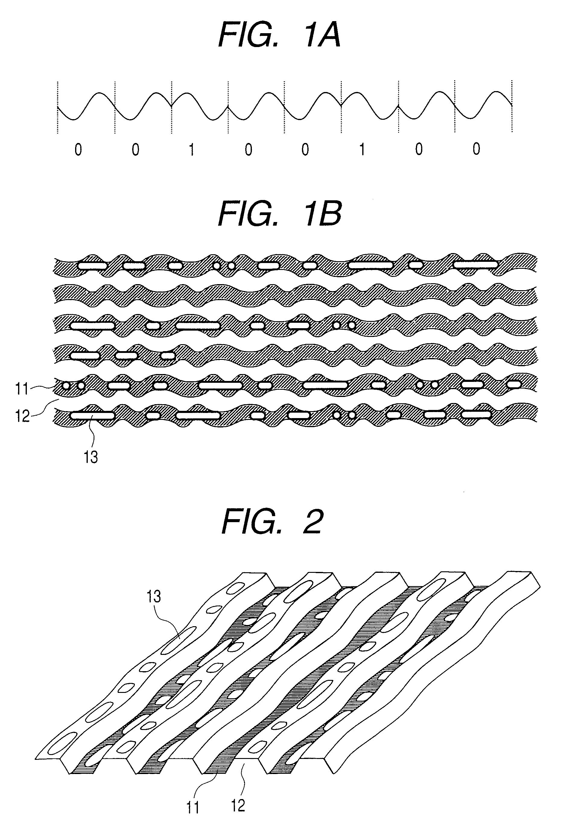
[0062]FIG. 2 is a partly enlarged view of an optical disc according to an embodiment of the invention. Respective information tracks include a groove 11 and land 12, spirally provided on a substrate in disc-like shape, respectively. User information is recorded as recording marks 13 having different reflectances in both the land 12 and groove 11. A track interval (an average distance between the respective centers of a groove track and land track, adjacent to each other) is 0.25 μm. The groove 11 is a grooved part provided on the substrate, and the grooved part is about 40 nm deep. With the present embodiment, since it is assumed that recording / reproduction are executed by an optical head with a numerical aperture of about 0.85 at wavelength of about 405 nm, the groove depth of about 40 nm is substantially equal to an optical distance corresponding to one sixth of the wavelength. The grooved part is formed so as to undergo minute displacements (wobbles) in the radial direction at am...

third embodiment

[0077] An example of an optical recording and reproduction system using the optical disc according to the second embodiment of the invention is described hereinafter with reference to FIG. 10. FIG. 11A and 11B are block diagrams showing the optical recording and reproduction system employing an optical recording format of the invention. Light emitted from a laser light source 625 (in the case of the present embodiment, with a wavelength at about 405 nm), which is a part of an optical head 620, passes through a collimating lens 624, and is collimated into substantially parallel light beams 622. The light beams 622 are irradiated on the underside of an optical disc 610 through an objective lens 623, thereby forming an optical spot 621. Thereafter, the light beams 622 are guided to a detector 626 for a servo, and a division detector 627 via a beam splitter 628, a hologram element 629, and so forth. Signals from the respective detectors are turned into servo signals such as a tracking e...


PUM


Abstract

An information recording medium having a plurality of tracks, wherein the respective tracks at least include: a plurality of segments, and having redundancy of identical information being maintained in at least two of the segments of the same track.

Description

CROSS REFERENCE TO RELATED APPLICATION [0001] This is a continuation of U.S. application Ser. No. 10 / 639,724, filed Aug. 13, 2003. This application relates to and claims priority from Japanese Patent Application No. 2003-056518, filed on Mar. 4, 2003. The entirety of the contents and subject matter of all of the above is incorporated herein by reference.FIELD OF THE INVENTION [0002] The invention relates to a recording format of an information recording medium, that is, an information recording medium wherein address information for identification of recording areas is disposed, and an information reproduction method using the information recording medium. BACKGROUND OF THE INVENTION [0003] A track structure of a conventional optical disc is described by way of example hereinafter with reference to FIGS. 3 and 4. There are alternately disposed a plurality of groove tracks 3 and land tracks 4 on a disc-like recording medium in the direction of a radius of the disc-like recording medi...

Claims


Application Information

Patent Timeline
IPC IPC(8): G11B3/70G11B20/10G11B7/00G11B7/005G11B7/007G11B7/24G11B20/12G11B20/14G11B27/10G11B27/19G11B27/24
CPCG11B7/00718G11B2220/2541G11B7/24082G11B20/1217G11B20/1403G11B27/10G11B27/19G11B27/24G11B2020/1239G11B2020/1265G11B2020/1268G11B2020/1292G11B2220/20G11B2220/213G11B2220/216G11B7/00745
Inventor MIYAMOTO, HARUKAZUKUDO, HIROMIMAEDA, TAKESHI
Owner MIYAMOTO HARUKAZU
Why Eureka
Try Eureka