Method for machining a workpiece

a technology for machining and workpieces, applied in the direction of grinding drives, manufacturing tools, mechanical equipment, etc., can solve the problems of increasing land costs, increasing fundamental construction costs, and high installation costs, so as to achieve optimal reduction of initial costs and running costs of production lines

Active Publication Date: 2007-10-04
KOMATSU NTC LTD
View PDF10 Cites 13 Cited by
  • Summary
  • Abstract
  • Description
  • Claims
  • Application Information

AI Technical Summary

Benefits of technology

[0020]In the method for machining a workpiece pertaining to the aspect of the invention of claim 2, because the work serving as the target for machining is a crankshaft starting material, similarly to the method for machining a workpiece pertaining to the aspect of the invention of claim 1, the initial costs and running costs of the production line can be optimally reduced.

Problems solved by technology

However, the large number (six in total) of machine tools for which equipment is required of a conventional production line such as the one described above carries an inherent problem of very high installation costs associated with construction of the production line (initial establishment costs) and running costs associated with actual operation of the production line.
That is to say, there are unavoidable equipment costs associated with the six machine tools and the loaders provided between the machine tools in the construction of the production line and, furthermore, there are increased land costs as well as increased fundamental construction costs associated with the greater space required for securing the factory building area for provision of the production line.
In addition, a large number of machine tools (six in total) means a large quantity of electrical power energy is consumed in the operation of the production line and, in addition, apart from the costs necessitated by the processing of the scraps and so on discharged from each of the machining tools, there are unavoidable upkeep costs associated with maintenance and inspection of each machine tool.

Method used


Image

  • Method for machining a workpiece
  • Method for machining a workpiece
  • Method for machining a workpiece

Examples


Embodiment Construction

[0042]The present invention will be hereinafter described in detail with reference to drawings illustrating an embodiment thereof.

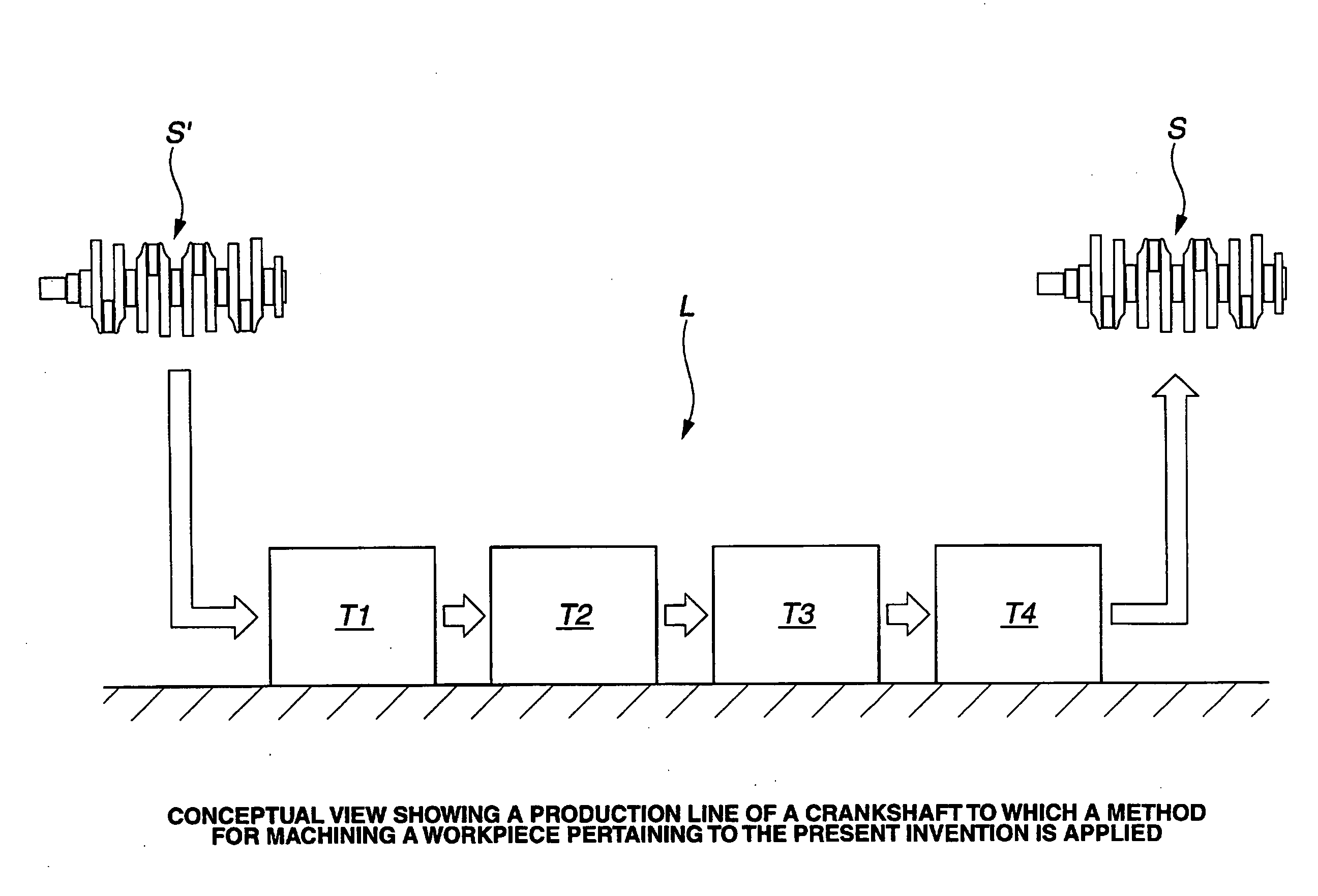
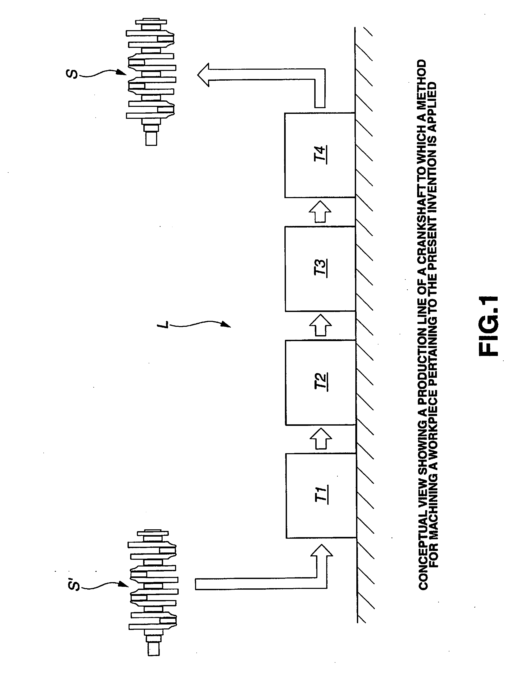
[0043]FIG. 1 to FIG. 19 show one example of the application of a method for machining a workpiece pertaining to the present invention in a crankshaft production line.

[0044]The configuration of the crankshaft serving as the target for machining is fundamentally identical to the crankshaft S shown in FIG. 20, and the description of the crankshaft S in the explanation provided hereinafter is given with reference to FIG. 20.

[0045]In addition, the crankshaft starting material serving as the workpiece on which the machining is to be actually administered is a forged product that, with a cutting allowance in mind, is manufactured slightly larger than the crankshaft S.

[0046]FIG. 1 depicts the machining sequence from the crankshaft starting material S′ manufactured by forging to when a semi-finish machining step of pins P1 to P4 of the crankshaft S are carried out...


PUM

PropertyMeasurementUnit
center angleaaaaaaaaaa
electrical poweraaaaaaaaaa
circumferenceaaaaaaaaaa

Abstract

A method for machining a workpiece in which a machine tool comprising a first and a second chuck devices is employed to machine the workpiece, the machine tool being used in which the first and the second chuck devices comprise a chuck main body, plural chuck jaws, a chuck jaw drive body, and a pressing member, the method comprising: machining a clamp part of the other end part of the workpiece in a state where one end part of the workpiece is clamped by the first chuck device; machining a clamp part of the one end part of the workpiece in a state where the clamp part of the other end part of the workpiece is clamped by the second chuck device; and executing desired machining on the workpiece in a state where each of the clamp parts are clamped by each of the chuck devices.

Description

BACKGROUND OF THE INVENTION[0001]1. Field of the Invention[0002]The present invention relates to a method for machining a workpiece employing a machine tool comprising a first chuck device for clamping one end part of a workpiece and a second chuck device for clamping the other end part of the workpiece, and more particularly to a method for machining a workpiece suitable for application in a crankshaft production line.[0003]2. Description of the Related Art[0004]Solid-type crankshafts which serve as a machine component part of an engine are normally manufactured by cutting and grinding a forged crankshaft starting material manufactured by employing machine tools, and the machining and manufacture of a crankshaft of a complex shape necessitates the implementation of a large number of machining steps employing a range of machining tools.[0005]As is well known, a common crankshaft S as shown in FIG. 20 comprises a predetermined number of arms (crank arms) A1 to A8 to which journals (m...

Claims


Application Information

Patent Timeline
Patent Type & Authority Applications(United States)
IPC IPC(8): B23C3/00
CPCB23B5/18Y10T82/10B23B31/16266B23B2231/22B23B2270/12B23D37/005Y10T409/30756Y10T279/26Y10T82/19Y10T409/303808Y10T279/17025Y10T279/1291Y10T29/5114Y10T279/18Y10T29/49286Y10T29/49996B23B31/16262B23P15/00B23P17/00
Inventor SHOJI, MASAHIROSHIMOMURA, MASUMI
Owner KOMATSU NTC LTD
Why Eureka
Try Eureka