Bone anchoring assembly

a technology of bone anchoring and assembly, which is applied in the field of bone anchoring assembly, can solve the problems of time-consuming procedure, achieve the effect of convenient temporary fixation, convenient temporary fixation, and sufficient strength

Inactive Publication Date: 2007-10-04
BIEDERMANN TECH GMBH & CO KG
View PDF7 Cites 131 Cited by
  • Summary
  • Abstract
  • Description
  • Claims
  • Application Information

AI Technical Summary

Benefits of technology

[0008] A bone anchoring assembly according to the disclosure provides a large clamping force on the rod by the application of only a small torque via the locking element when compared to the fixation of a rod via frictional locking. This facilitates a temporary fixation of the rod via the application of small torques on the locking element during the process of adjusting and re-adjusting the position of the rod. Due to a form-locking connection, the temporary fixation has sufficient strength to withstand loosening when manipulations are carried out on the rod. Further, the temporary fixation can be loosened quickly by only slightly turning back the inner screw. Therefore, the bone anchoring device is suitable in the application of correcting spinal deformities such as scoliosis which during surgery require re-adjusting the position of the rod several times until it is finally locked.
[0010] Since a pre-fixation of the rod is achieved with the application of a lower torque, a splaying of the legs of the receiving part is reduced.

Problems solved by technology

This procedure is time consuming since always two nuts have to be adjusted.

Method used


Image

  • Bone anchoring assembly
  • Bone anchoring assembly
  • Bone anchoring assembly

Examples


first embodiment

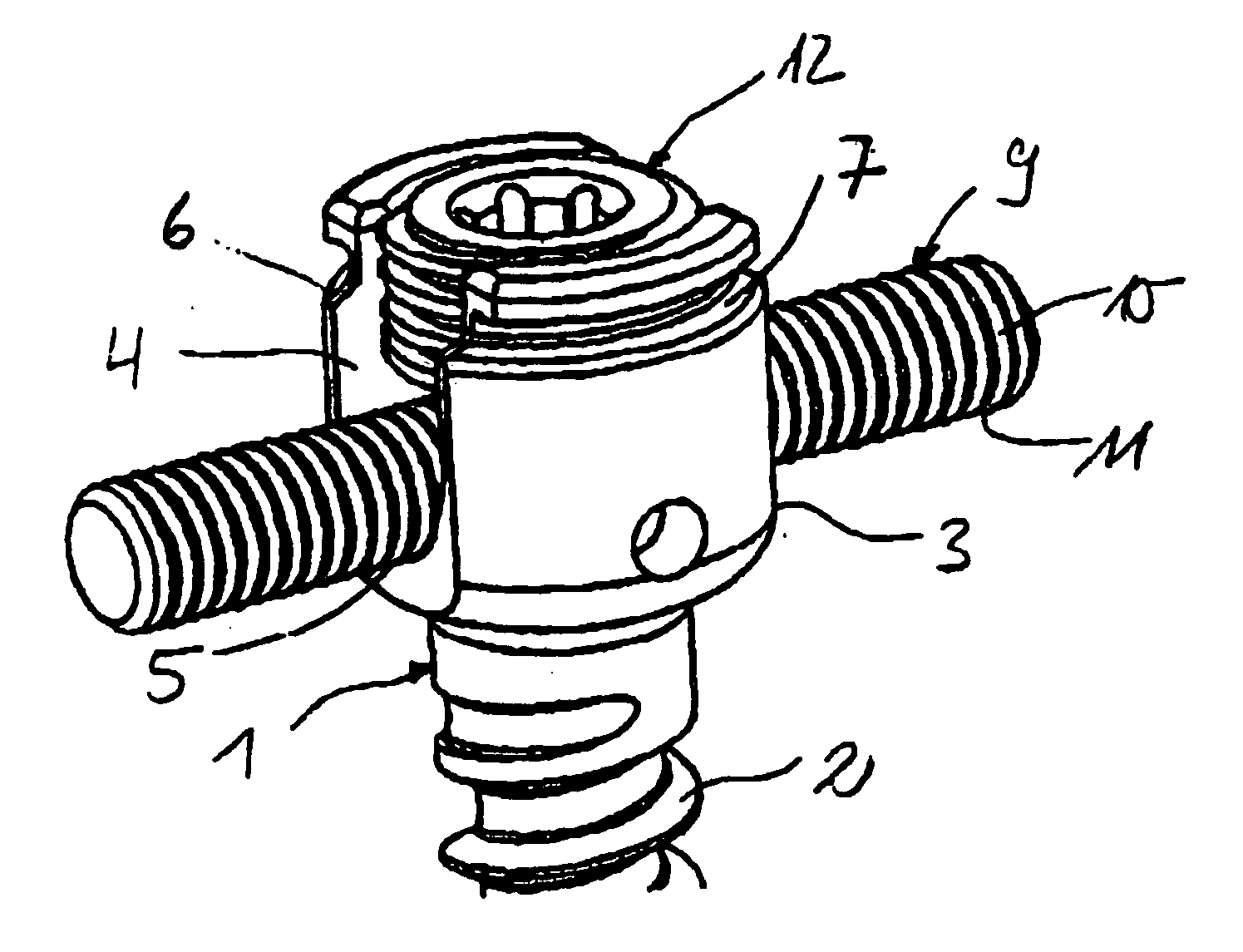
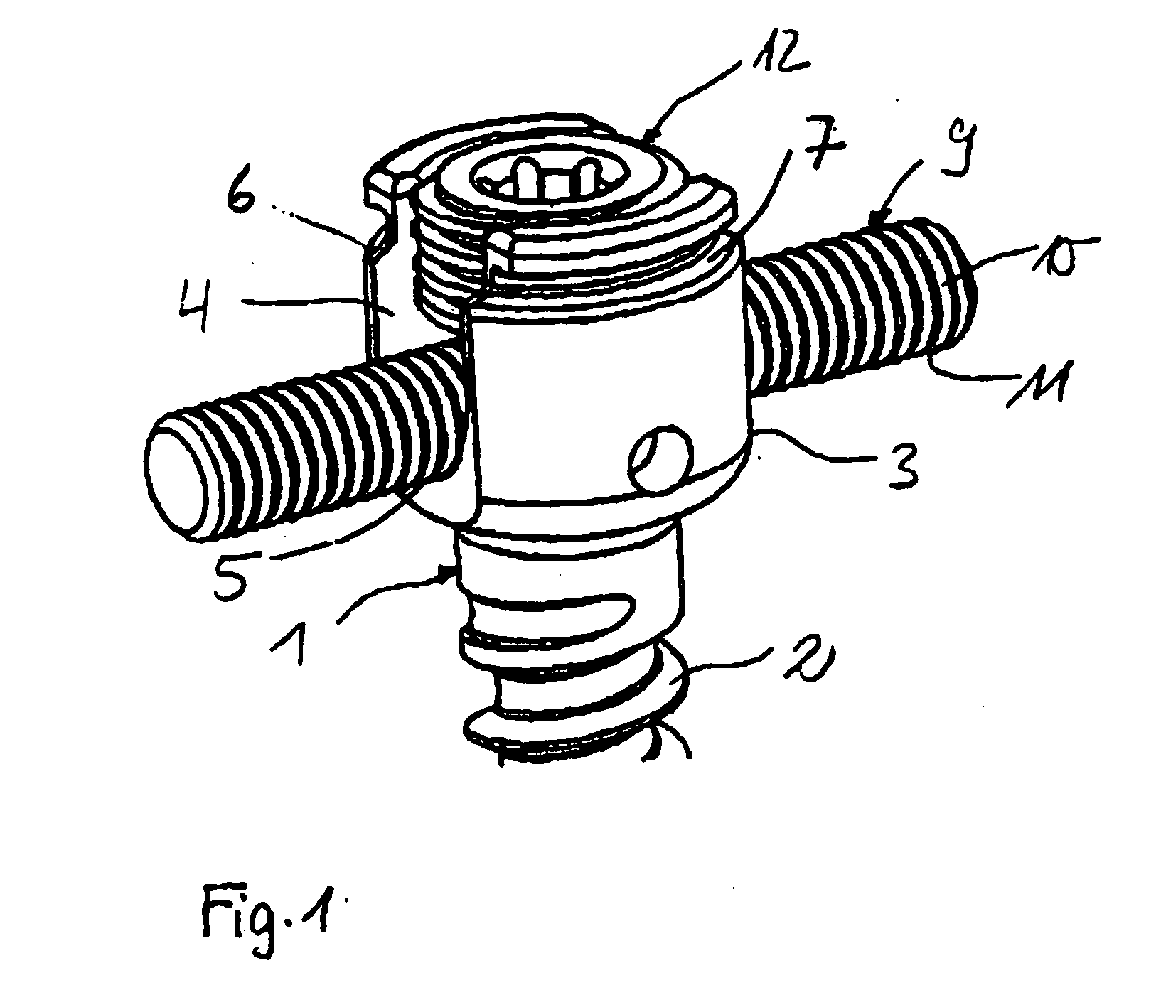
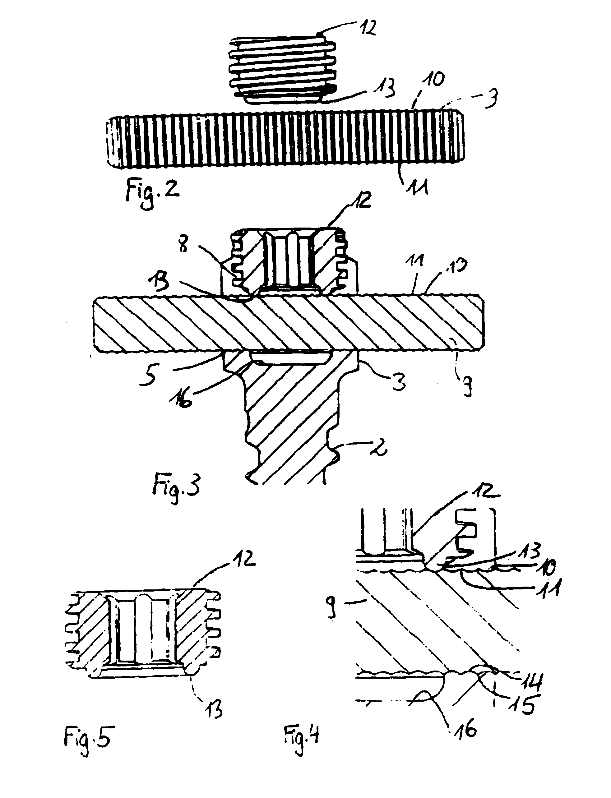
[0029] the anchoring assembly shown in FIGS. 1 to 7 comprises a bone anchoring element 1 having a threaded shaft 2 and a receiving part 3. The receiving part 3 is substantially cylindrical and has a U-shaped recess 4 with a bottom 5 at the side of the threaded shaft. By means of the U-shaped recess 4, two free legs 6, 7 are formed. A bore having an internal thread 8 is provided within the channel formed by the U-shaped recess 4 and formed coaxially with the center axis of the threaded shaft 2. The internal thread 8 can have any known thread shape. A flat thread or a negative angle thread however can be used so as to prevent splaying of the legs 6, 7.

[0030] The anchoring assembly further comprises a longitudinal rod 9 with a structured surface. In the embodiment shown, the rod has a circular cross section. The structure is a ratchet-type structure comprising a plurality of circumferential grooves 10 separated by circumferential crests 11.

[0031] In order to allow the anchoring of the...

second embodiment

[0050] In a further modification of the second embodiment, the head and the rod can be fixed independently. In this case the pressure element has instead of the cylindrical recess a U-shaped recess by means of which legs are formed which extend above the rod. The locking member comprises a first screw pressing on the pressure element only and having a threaded coaxial bore in which a set screw is provided which comes into engagement with the rod.


PUM


Abstract

A bone anchoring assembly for use in spinal surgery or trauma surgery includes an anchoring element having a shaft and a receiving part having a substantially U-shaped cross-section with a base connected to said shaft and two free legs forming a channel for receiving a rod having an at least partially structured surface. The bone anchoring assembly further includes a locking member cooperating with the receiving part for locking said rod in the channel. At least on the locking member or in the receiving part an engagement portion for engaging said structured surface of the rod is provided. The locking member, the rod and the receiving part cooperate in such a manner that as soon as the engagement portion comes into engagement with the structured surface the rod is held in the receiving part in a form-locking manner preventing movement of the rod.

Description

CROSS-REFERENCE TO RELATED APPLICATION(S) [0001] The present application claims the benefit of U.S. Provisional Patent Application Ser. No. 60 / 758,342, filed Jan. 11, 2006, and claims priority from EP 06000496.7, filed Jan. 11, 2006, the disclosures of which are incorporated by reference herein.BACKGROUND [0002] The invention relates to a bone anchoring assembly for use in spinal surgery or trauma surgery. In particular, the invention relates to a bone anchoring assembly comprising at least two bone anchoring elements with a receiving part to receive a rod and such a rod for connecting the bone anchoring elements wherein the rod is fixed in the receiving part by means of a form-locking connection. [0003] U.S. Pat. No. 5,207,678 discloses a pedicle screw comprising a screw and a receiver member to connect the screw with a rod. The rod is a threaded rod which is locked in the receiver member by means of two nuts engaging the outside of the receiver member and being adjustable on the t...

Claims


Application Information

Patent Timeline
Patent Type & Authority Applications(United States)
IPC IPC(8): A61F2/30
CPCA61B17/7002A61B17/7004A61B17/7037A61B17/7032A61B17/7005A01K49/00A01K57/00
Inventor HARMS, JURGENMATTHIS, WILFRIEDRAPP, HELMARBIEDERMANN, LUTZ
Owner BIEDERMANN TECH GMBH & CO KG
Why Eureka
Try Eureka