Cervical fusion apparatus and method for use

a fusion apparatus and cervical technology, applied in the field of cervical fusion apparatus and method for use, can solve the problems of increased pressure, unfavorable symptoms such as pain, numbness, weakness, disordered reflex symptoms, etc., and achieve the effect of prolonging healing time, reducing pain, and reducing pain

Inactive Publication Date: 2007-10-04
THE CLEVELAND CLINIC FOUND
View PDF4 Cites 80 Cited by
  • Summary
  • Abstract
  • Description
  • Claims
  • Application Information

AI Technical Summary

Problems solved by technology

In the neck, degeneration of discs often causes vertebrae to undesirably compress their associated spinal nerves, causing uncomfortable symptoms such as pain, numbness, weakness, and disordered reflex symptoms.
However, currently available plates are generally larger than needed to simply maintain adjacent cervical vertebrae in fixed orientation in most patients.
These oversized structures require a relatively large incision and dissection for insertion, which may be complex and time-consuming for the surgeon and require broader dissection of tissues in the neck and greater pressure on tissues being moved out of the way.
This generally results in longer healing time and a larger risk of complications in the patient than in a smaller incision and dissection.
Disturbance of these delicate throat structures often leads to hoarseness, pain, and swallowing difficulties.

Method used


Image

  • Cervical fusion apparatus and method for use
  • Cervical fusion apparatus and method for use
  • Cervical fusion apparatus and method for use

Examples


Embodiment Construction

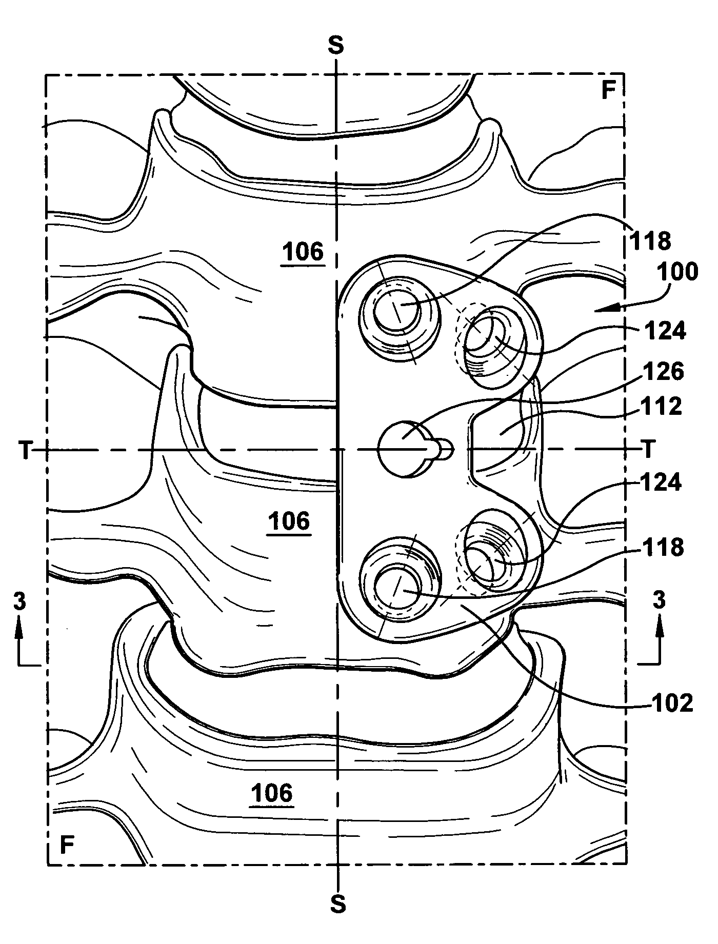
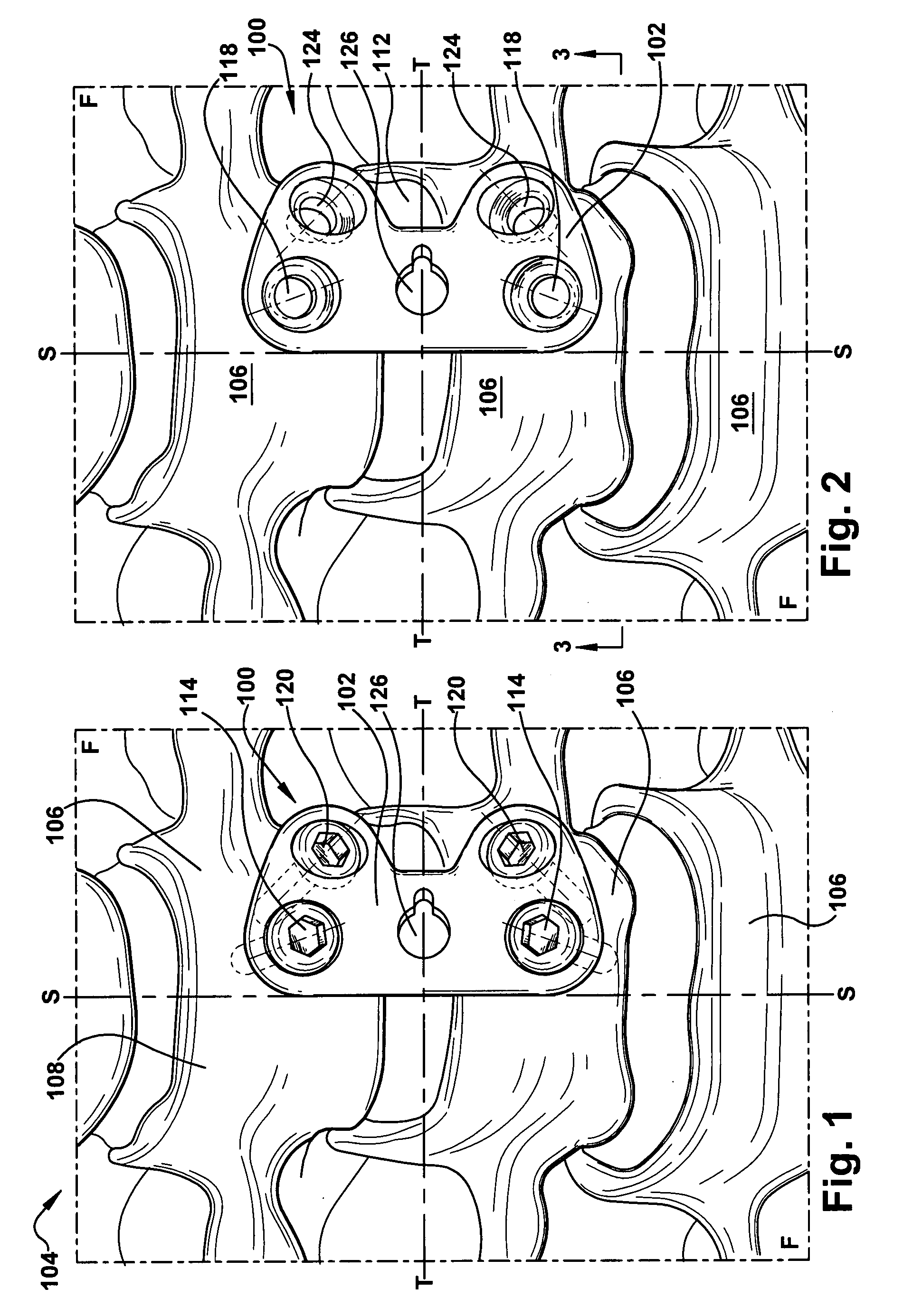
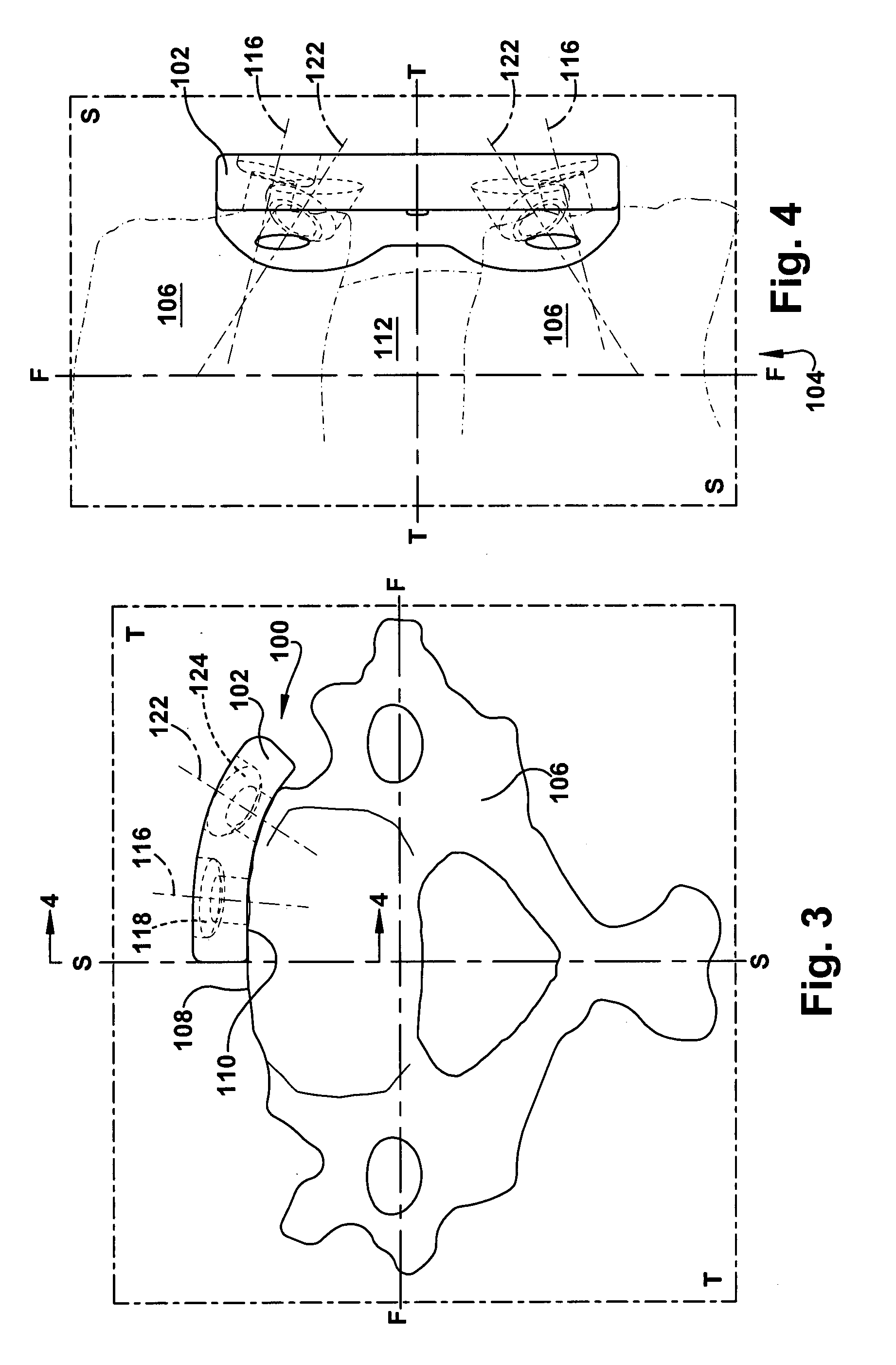
[0016]In accordance with the present invention, FIG. 1 depicts a frontal view of a cervical fusion apparatus 100. The cervical fusion apparatus 100 includes a cervical fusion plate 102, which is shown in FIG. 1 as being attached to a spinal column 104. The spinal column 104 includes a plurality of vertebrae 106, which may be cervical vertebrae.

[0017]In FIGS. 1-4, a known three-dimensional orthogonal coordinate system comprising a frontal plane (“F-F”), a sagittal plane (“S-S”), and a transverse plane (“T-T”) is illustrated in conjunction with the spinal column 104. Each of these three planes is perpendicular to the other two. While the frontal, sagittal, and transverse planes are depicted in the Figures as having certain positions in relation to the spinal column 104 for clarity of description, these planes may be defined in any desired relationship to the spinal column 104 as long as the planes maintain the orthogonal coordinate system as shown. For example, the transverse plane ma...


PUM


Abstract

In an exemplary embodiment of the present invention, a method of implanting a fusion plate, having at least two primary fastener openings, into a patient is described. According to the inventive method, a throat of the patient is dissected, providing access through the throat dissection to a spinal column of the patient. The fusion plate is inserted into the throat dissection, and the fusion plate is then positioned in an asymmetrical relationship with a sagittal plane of the spinal column. A first primary fastener is inserted through a first primary fastener opening of the fusion plate and into the first vertebra. A second primary fastener is inserted through a second primary fastener opening of the fusion plate and into the second vertebra. A cervical fusion apparatus is also disclosed.

Description

RELATED APPLICATION[0001]This application claims priority from U.S. Provisional Application No. 60 / 778,534, filed Mar. 2, 2006, the subject matter of which is incorporated herein by reference.TECHNICAL FIELD[0002]The present invention relates to an apparatus and method for use in retaining vertebrae of a spinal column in a desired spatial relationship. The present invention is particularly adapted for use in retaining cervical vertebrae of a human spinal column in a desired spatial relationship so that fusion of the cervical vertebrae can occur.BACKGROUND OF THE INVENTION[0003]The vertebrae of the human spinal column are commonly classified by position into cervical (neck), thoracic (chest), and lower back (lumbar) vertebrae, with intervertebral discs separating each vertebra from the adjacent vertebrae. In the neck, degeneration of discs often causes vertebrae to undesirably compress their associated spinal nerves, causing uncomfortable symptoms such as pain, numbness, weakness, an...

Claims


Application Information

Patent Timeline
Patent Type & Authority Applications(United States)
IPC IPC(8): A61F2/30
CPCA61B17/7059
Inventor MCLAIN, ROBERT F.
Owner THE CLEVELAND CLINIC FOUND
Why Eureka
Try Eureka