
Compound offset handle

Active Publication Date: 2007-10-04
HOWMEDICA OSTEONICS CORP
View PDF17 Cites 63 Cited by
  • Summary
  • Abstract
  • Description
  • Claims
  • Application Information

AI Technical Summary

Problems solved by technology

However, these handles are designed for use in hip replacement procedures that require either a large incision or a posterior approach in order to gain access to the femur, both of which cause severe trauma to the area surrounding the hip joint increasing the patient's pain and recovery time, and can result in increased risk to the patient.
Traditional instrument handles, such as straight or single-plane angled handles, are not conducive to use in hip replacement surgery using an anterior approach because this procedure typically does not allow for straight-line access to the femoral canal, especially when using minimally-invasive surgery (MIS) techniques such as decreased incision size.
In particular, problems can arise from the use of traditional handles with respect to alignment of the shaping instrument in the femoral canal, which can cause fracture or misalignment of the femoral implant.
Furthermore, problems can arise related to tissue damage from extreme pressure that must be applied to the handle while “fighting” against the tissue for alignment of the shaping instrument within the femoral canal.
However, because the handle has two sections that are orthogonal to the direction of movement of the handle, the handle still interferes with the tissue surrounding the femoral medullary canal, resulting in damage thereto.
Furthermore, the severity of the bends used in the handle results in a significant loss of linear impaction force from the proximal end of the handle, where the force is applied, to the instrument, where the force acts.
While shaping the femoral medullary canal, it is necessary to minimize torque within the shaping handle because such torque is ultimately applied to the bone, which can cause breakage of the bone or misalignment of the implant.
At the very least, the loss of the linear force applied to the handle makes it more difficult to shape the medullary canal for acceptance of the implant because the instrument tends to pitch or yaw within the medullary canal.
Several variations of such locking mechanisms have been previously developed, but these locking mechanisms are only designed to work with straight or single-plane handles.

Method used


Image

  • Compound offset handle
  • Compound offset handle
  • Compound offset handle

Examples


Embodiment Construction

[0032] In describing the preferred embodiments of the subject matter illustrated and to be described with respect to the drawings, specific terminology will be resorted to for the sake of clarity. However, the invention is not intended to be limited to the specific terms so selected, and it is to be understood that each specific term includes all technical equivalents which operate in a similar manner to accomplish a similar purpose.

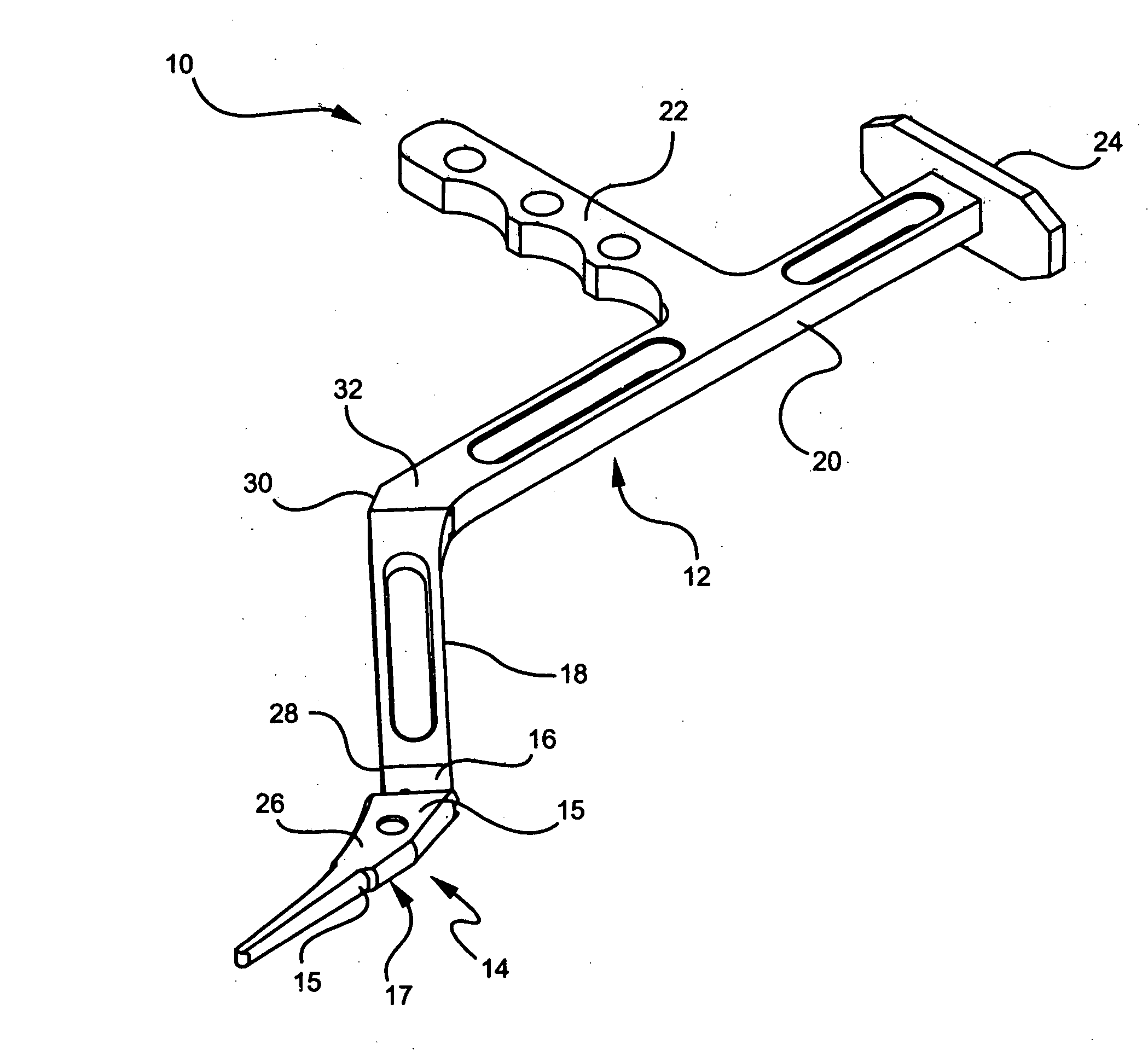
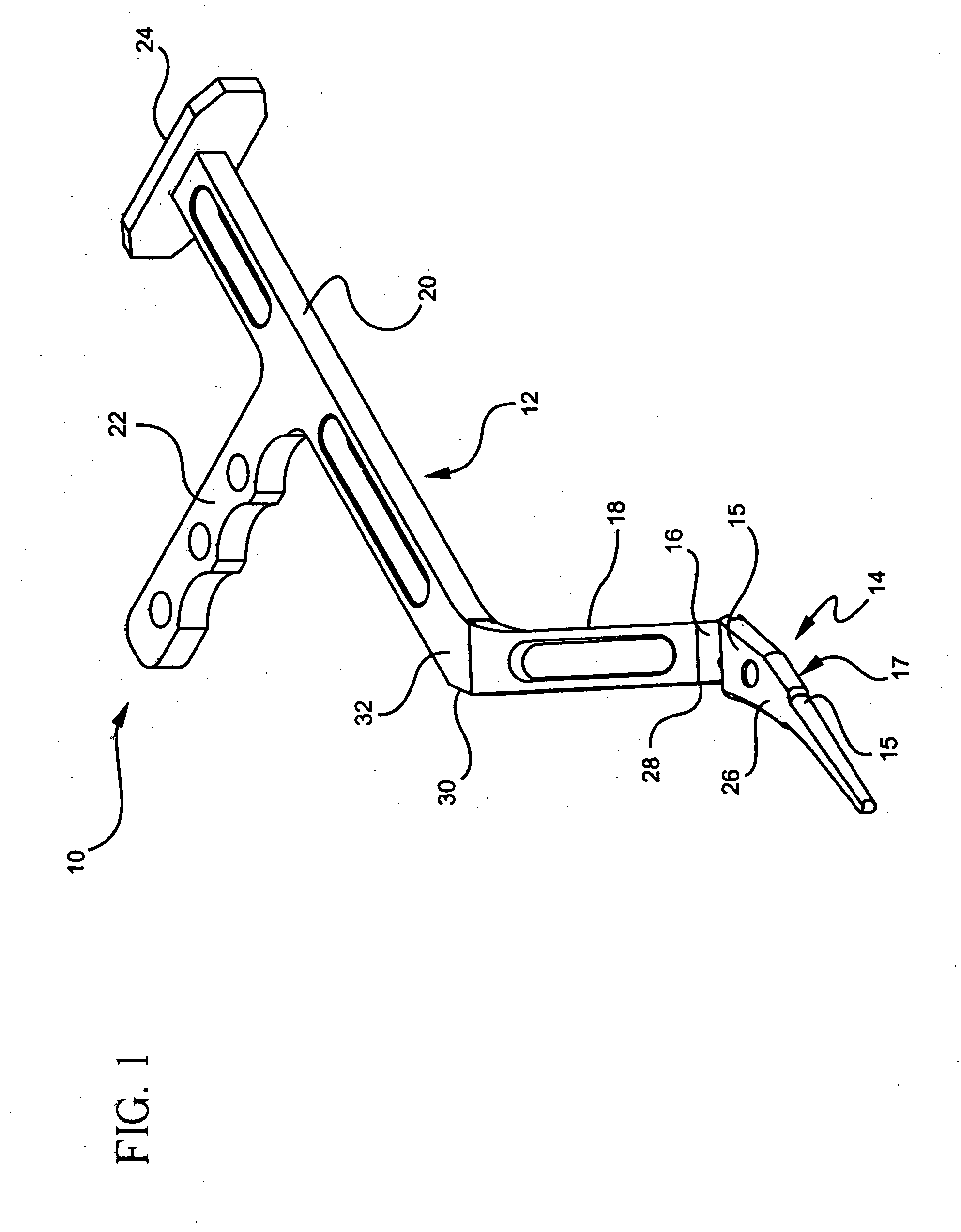
[0033] Referring to the drawings, wherein like reference numerals represent like elements, there is shown in FIG. 1, in accordance with one embodiment of the present invention, a surgical device designated generally by reference numeral 10. In describing preferred embodiments of the device of the present invention, reference will be made to the directional nomenclature used in describing the human body. It is noted that this nomenclature is used only for convenience and that it is not intended to be limiting with respect to the scope or structure of the...


PUM


Abstract

A device for use on a patient during surgery including a distal portion, a transition portion, and a proximal portion is disclosed. The distal portion is adapted to attach to an implement having a proximal portion. The transition portion is angled toward an anterior direction and a medial direction with respect to the implement, the proximal portion of the handle being connected to the transition portion and extending in a proximal direction substantially parallel to the implement.

Description

BACKGROUND OF THE INVENTION [0001] A total or partial hip replacement procedure is sometimes necessary to repair diseased or damaged parts of the hip joint, and in particular, the femoral head or the acetabular cup of the hip joint. During replacement of the femoral head, the diseased or damaged head is removed and the remaining portion of the femur is shaped to receive the stem of an implant which extends into the medullary canal of the bone. A prosthetic, spherical or ball-shaped head is attached to the top of the stem and replicates the anatomy of the removed femoral head, fitting into either the remaining acetabular cup or an artificial replacement therefore. [0002] Shaping of the femoral canal is accomplished using various shaping instruments in the form of femoral rasps or broaches. Generally, such rasps or broaches are designed to match the shape of the stem to be used in the replacement implant so that the femur can be shaped to securely receive the implant. Shaping instrume...

Claims


Application Information

Patent Timeline
IPC IPC(8): A61B17/00
CPCA61B17/1659A61F2002/4628A61F2/36A61F2/4606A61F2/4607A61F2/461A61F2/4612A61F2002/30331A61F2002/30476A61F2002/4629A61F2220/0025A61F2220/0033A61B17/1668A61B17/164A61F2002/4627A61B2017/0046
Inventor BASTIAN, ADAMLAVIGNA, NICHOLAS JON
Owner HOWMEDICA OSTEONICS CORP
Features
  • Generate Ideas
  • Intellectual Property
  • Life Sciences
  • Materials
  • Tech Scout
  • Unparalleled Data Quality
  • Higher Quality Content
  • 60% Fewer Hallucinations
Learn More