Composite joint implant

a joint implant and composite technology, applied in knee joints, prostheses, medical science, etc., can solve the problems of large overall cost increase of trial components, large secondary operation required to impart the necessary geometry onto these materials, and relatively heavy components

Active Publication Date: 2007-10-04
HOWMEDICA OSTEONICS CORP
View PDF28 Cites 52 Cited by
  • Summary
  • Abstract
  • Description
  • Claims
  • Application Information

AI Technical Summary

Benefits of technology

[0009] In an alternative embodiment, the shell is made from carbon fiber, which can include either long or short fibers. Further, the shell may include a layer of polymer overmolded on the carbon fiber.

Problems solved by technology

However, the processing required to impart the necessary geometry onto these materials requires many secondary operations, such as CNC grinding or polishing.
Each of these secondary operations is, thus, costly and time consuming, leading to a large overall cost increase of trial components.
In addition to the cost associated with processing the cast materials of typical trials, the density of the material can be quite high, resulting in a relatively heavy component.
Each trial component may weigh approximately 1-1.5 pounds, a weight which becomes problematic due to the methods employed during TKR and THR procedures.
When combined with the other trays contained in the sterilization case, total case weight is significant.
The same problem applies for THR procedures: as with femoral sizing, proximal stem sizing must be performed interoperatively.

Method used


Image

  • Composite joint implant
  • Composite joint implant
  • Composite joint implant

Examples


Embodiment Construction

[0025] In describing the preferred embodiments of the subject matter illustrated and to be described with respect to the drawings, specific terminology will be resorted to for the sake of clarity. However, the invention is not intended to be limited to the specific terms so selected, and it is to be understood that each specific term includes all technical equivalents which operate in a similar manner to accomplish a similar purpose.

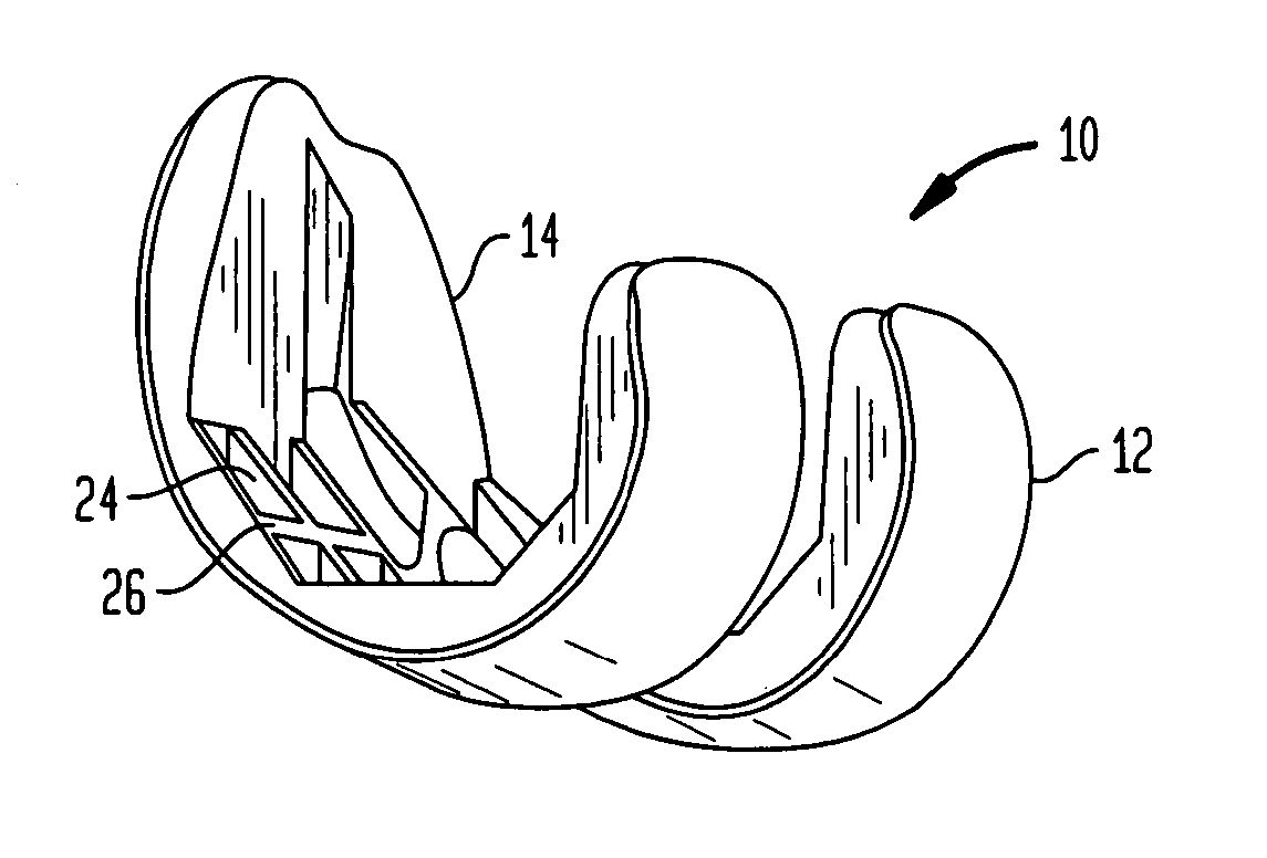
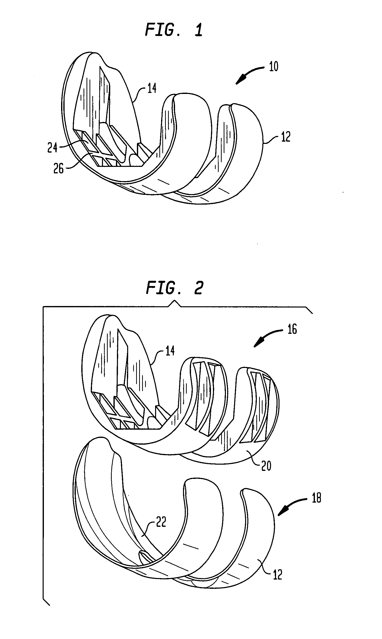
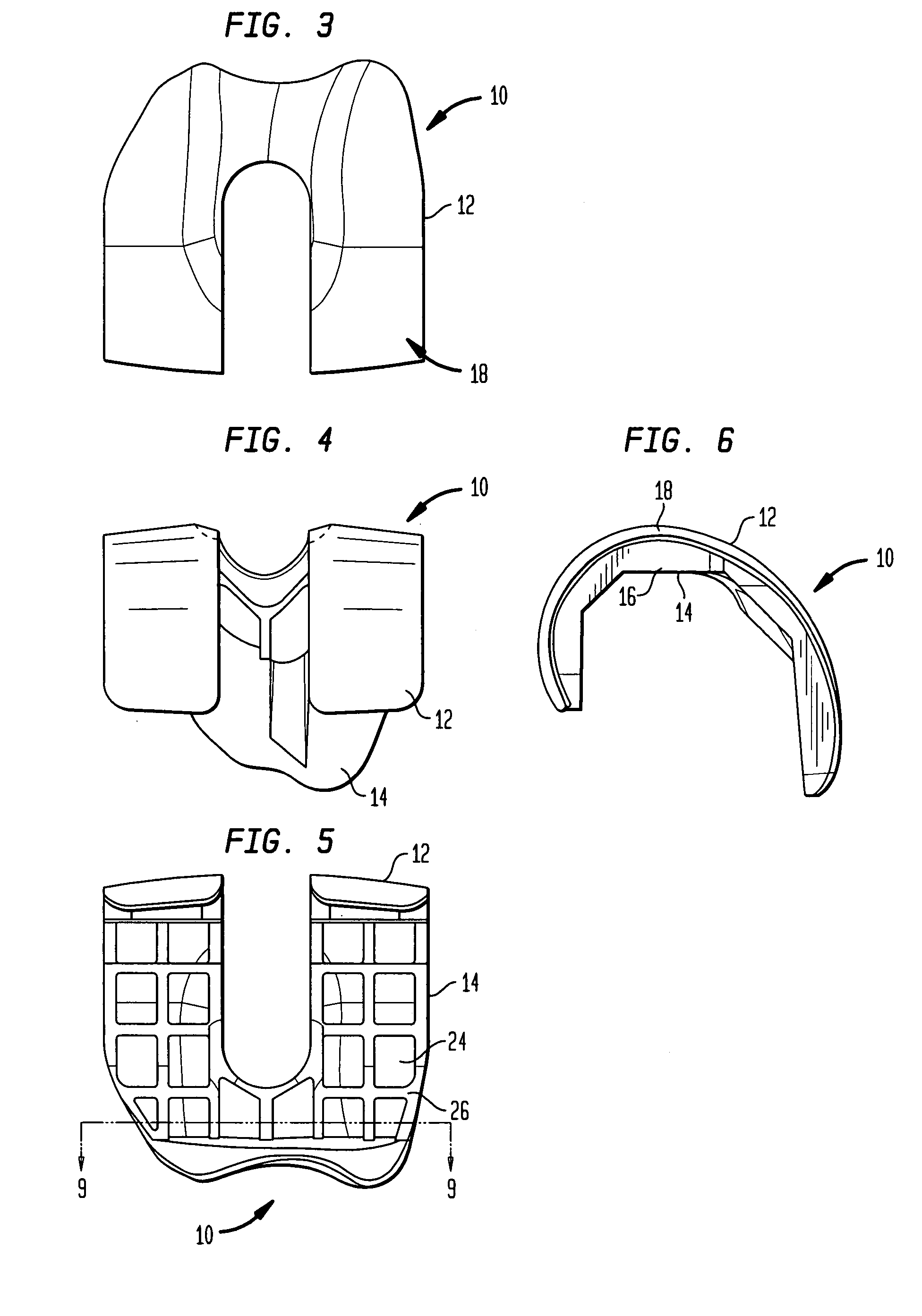
[0026] Referring to the drawings, wherein like reference numerals represent like elements, there is shown in FIGS. 1-6, in accordance with a preferred embodiment of the present invention, more particularly, a femoral implant 10 used during a TKR procedure. The particular implant shown is preferably used as a trial implant; however it may be used as any type of femoral implant. Generally, the implant of the present invention has two primary surfaces thereof, including an articulating surface 12, and a bone engaging surface 14. Preferably, articulating su...


PUM

PropertyMeasurementUnit
weightaaaaaaaaaa
weightaaaaaaaaaa
thicknessaaaaaaaaaa

Abstract

The present invention relates to a femoral component for use in connection with knee anthroplasty. The implant includes a support having a contoured inner bone engaging surface, and a shell affixed to the support. The shell has an outer surface spaced so as to provide an articulation surface for engaging the tibia that substantially replicates the shape of a femoral condyle, and an inner surface for receiving an outer surface of the support. The support bone engaging surface is structured to mate with a prepared surface of the distal femur and the support spaces the shell outer surface at a predetermined distance from the prepared surface.

Description

BACKGROUND OF THE INVENTION [0001] Total knee replacement (“TKR”) is a commonly-used procedure for correcting deformities and repairing damage to the knee joint. The procedure used for TKR is generally known in the art and includes many variations. Generally, such a procedure includes exposing the knee joint by forming at least one incision through the soft tissue in the knee area and retracting the wound. The joint is then resected, which includes removing the damaged portions of the joint. This typically includes removing one or both of the femoral condyles and / or the tibial plateau, which is typically accomplished by forming a series of cuts according to any one of various patterns. The cuts are typically made so that the bone can accept an artificial replacement for the resected portions of the joint. As the precise anatomy of the knee on which TKR is preformed varies significantly among patients, it is necessary to provide artificial replacements for the knee components in vari...

Claims


Application Information

Patent Timeline
Patent Type & Authority Applications(United States)
IPC IPC(8): A61F2/38
CPCA61F2/30767A61L27/425A61F2/30965A61F2/36A61F2/3662A61F2/3676A61F2/3859A61F2/4684A61F2002/30115A61F2002/30153A61F2002/30172A61F2002/30235A61F2002/30433A61F2002/30434A61F2002/30441A61F2002/30448A61F2002/30451A61F2002/30808A61F2002/30879A61F2002/30884A61F2002/30934A61F2002/30957A61F2002/30973A61F2002/30975A61F2002/3611A61F2002/3625A61F2220/0041A61F2220/005A61F2220/0058A61F2230/0006A61F2230/0019A61F2230/0052A61F2230/0069A61F2240/001A61F2310/00017A61F2310/00029A61F2310/00047A61F2310/00401A61F2310/00413A61F2310/00431A61L27/04A61L27/306A61F2/3094
Inventor WILLIAMS, PHILIP F. IIIDEMARIA, CHRISTOPHERLAGANIS, EDWARD J.LA ROSA, ANTHONY J.
Owner HOWMEDICA OSTEONICS CORP
Why Eureka
Try Eureka