

Disk enclosure
- Summary
- Abstract
- Description
- Claims
- Application Information
AI Technical Summary
Benefits of technology
Problems solved by technology
Method used
Image

Examples
Embodiment Construction
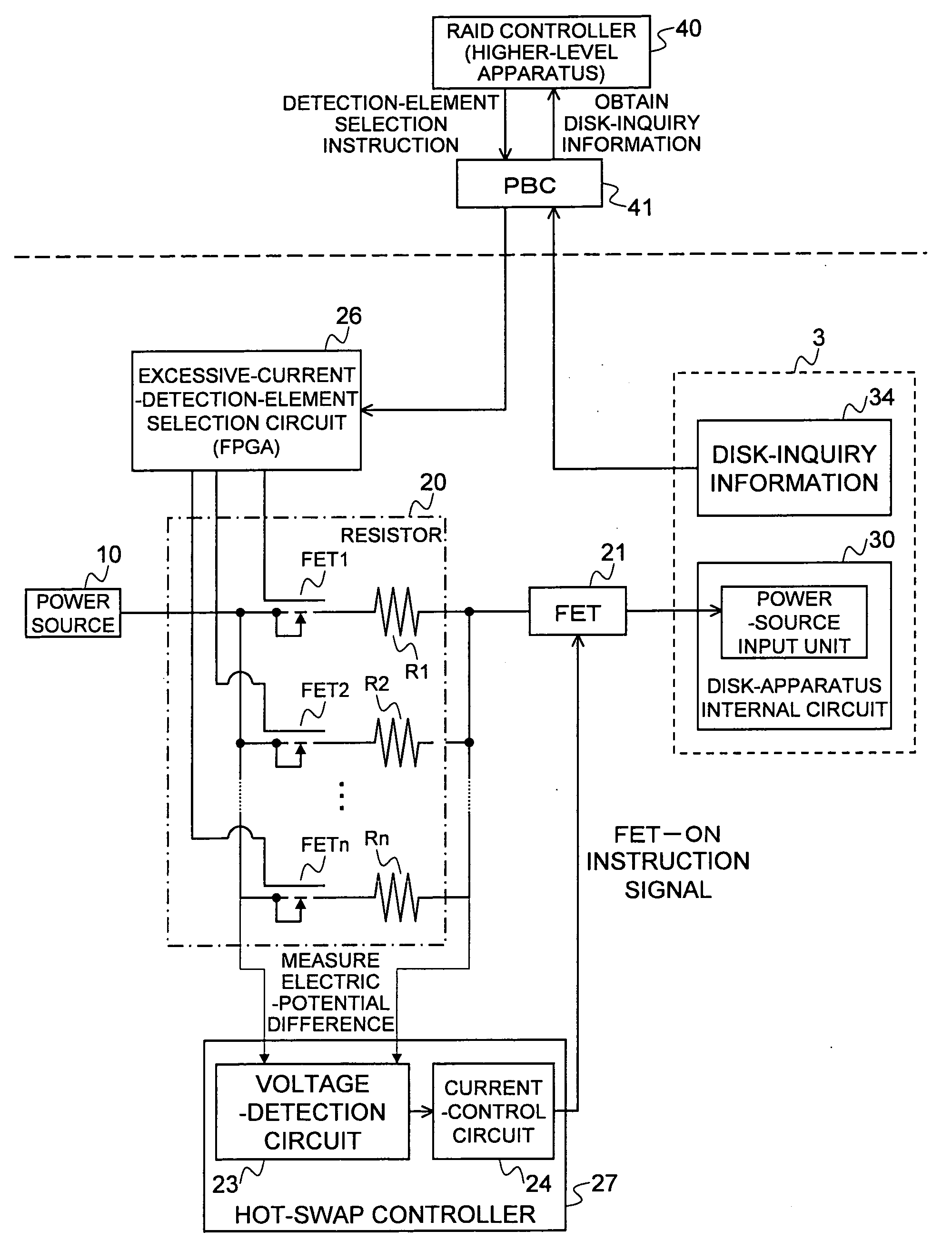
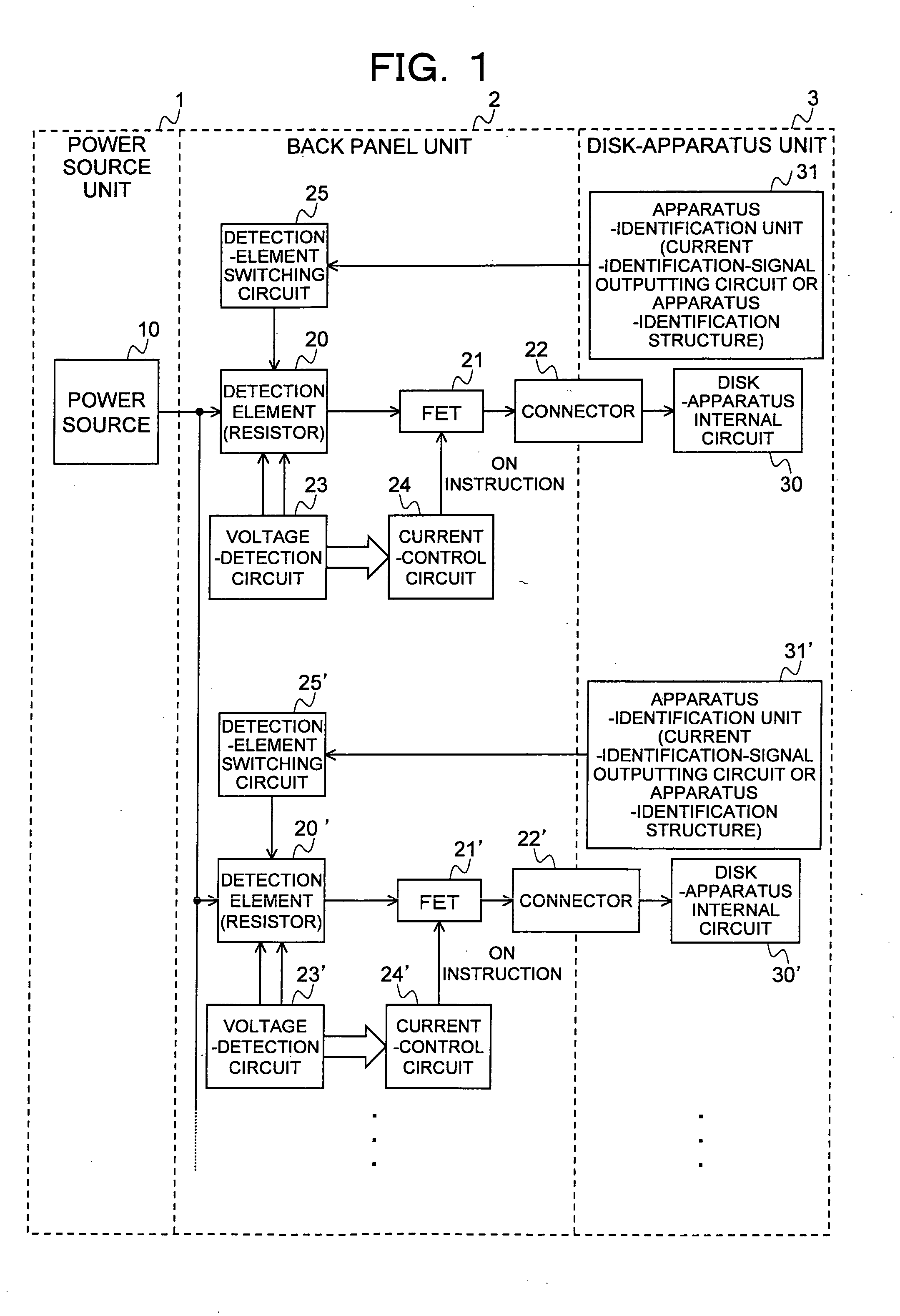
[0024]The present invention realize, in a disk enclosure containing a plurality of disk apparatuses, a unit that switches a detection resistance value to detect a current which flows to respective disk apparatuses, as described below.
[0025]According to a first aspect of the present invention, a signal indicating a consumption current value of a disk apparatus is added to the disk apparatus. On the other hand, in a disk enclosure, a selection circuit is provided which selects a detection resistance value according to the signal. A signal line is added to the disk apparatus itself or an active frame (a case of the disk apparatus) for storing the disk apparatus.
[0026]According to a second aspect of the present invention, a structure which can identify a consumption current is added to the active frame of the disk apparatus. In a disk enclosure, a circuit (for example, any device such as a switch, a sensor, or a reader is acceptable) that can identify the structure is provided as a sele...
PUM
 Abstract
Description
Claims
Application Information