Mine resistant armored vehicle

a technology of armored vehicles and armored vehicles, which is applied in the direction of shields, protective equipment, transportation and packaging, etc., can solve the problems of reducing the efficiency of energy being transferred to the vehicle at locations distant from the detonation point, affecting the safety of vehicles, and not being practicable to bury such devices in the anticipated tim

Inactive Publication Date: 2007-10-11
FORCE PROTECTION TECH
View PDF13 Cites 92 Cited by
  • Summary
  • Abstract
  • Description
  • Claims
  • Application Information

AI Technical Summary

Benefits of technology

[0014] It is further preferred that the angle of the V be a compound angle, having more than a single angle, with the angle of the V closest to the centerline of the vehicle being greater than the angle of the V adjacent the sides of the body. A most preferred embodiment has the angle of the V closest to the centerline approximately 120°, and the second angle approximately 90°.

Problems solved by technology

This can result in the mine defeating the armor and allowing the penetrator, debris or the blast energy to breach the armor and enter the vehicle.
A large ground clearance significantly reduces the amount of energy impinging on the bottom of the vehicle and reduces the efficiency of energy being transferred to the vehicle at locations distant from the detonation point of the mine.
In irregular or guerilla warfare, explosive devices often are fabricated from any available explosive materials and may not have the trigger mechanisms of manufactured anti-vehicle mines.
These irregular devices are commonly referred to as “roadside bombs” or “improvised explosive devices” or “IEDs.” It may not be practicable to take the time to bury such devices in the anticipated path of vehicles to be attacked.
As a result, the blast and material propelled by it tend to impinge laterally on the side of the target vehicle.
While any practical mine or improvised explosive device can be defeated by armor of sufficient strength and thickness, the extra armor is heavy and expensive, adds weight to the vehicle which, in turn places greater strain on the vehicle engine, and drive train.

Method used


Image

  • Mine resistant armored vehicle
  • Mine resistant armored vehicle
  • Mine resistant armored vehicle

Examples


Embodiment Construction

[0029] Reference will now be made in detail to the present preferred embodiments of the invention, examples of which are illustrated in the accompanying drawings.

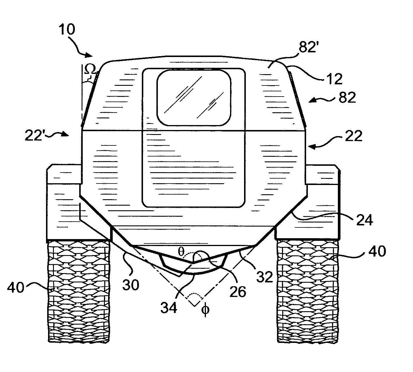
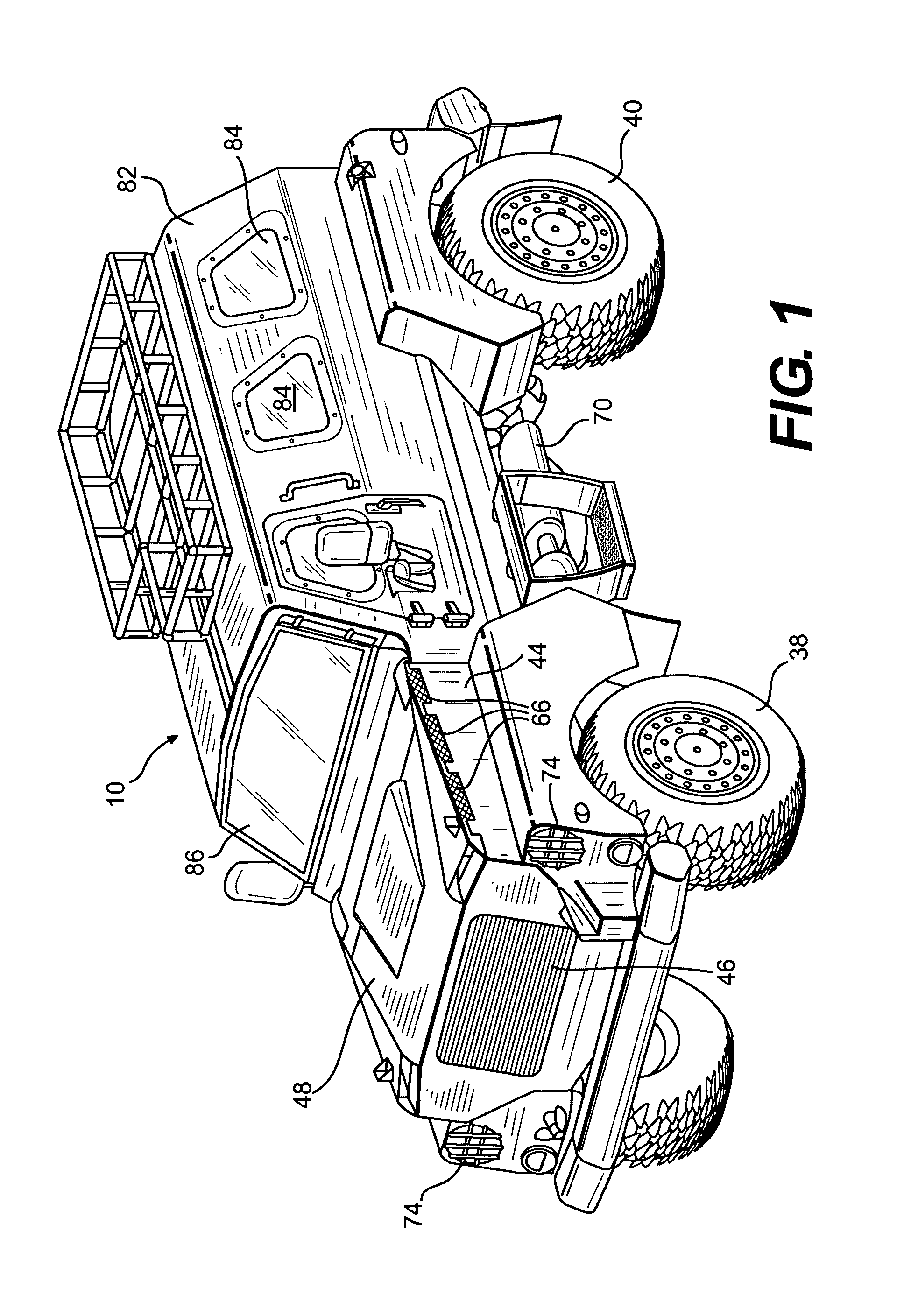
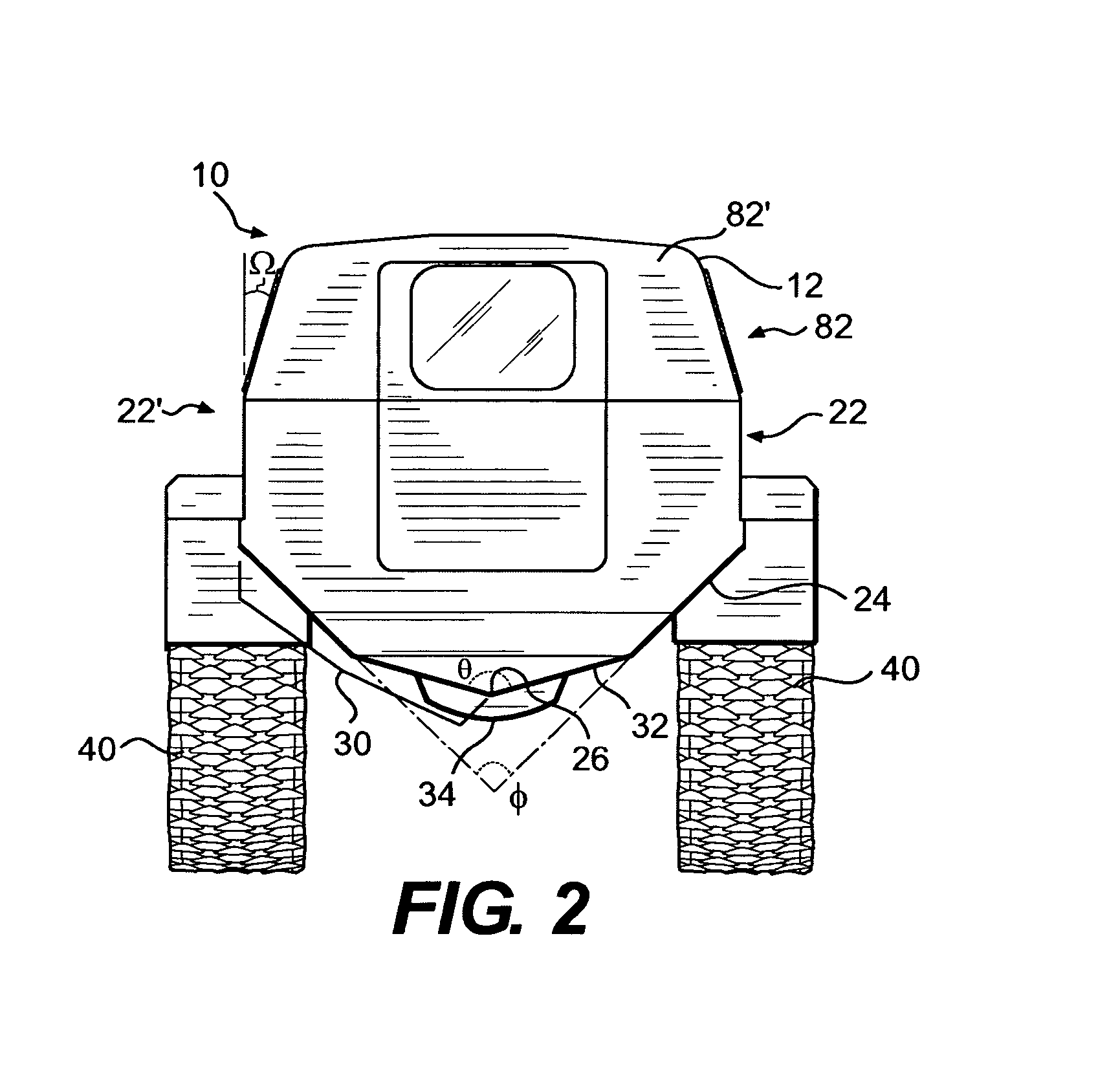
[0030] In accordance with the invention, there is provided a blast-resistant armored land vehicle that may include a monocoque body comprised of sheet material. In the context of the present invention the phrase “blast-resistant” means that the vehicle is particularly resistant to penetration by either the blast energy or material propelled by the blast energy from either a land mine that explodes beneath the vehicle or an explosive device that explodes laterally, in a generally horizontal direction. In the context of the present invention the phrase “land vehicle” means a vehicle intended primarily to propel itself on the surface of the ground. In the context of the present invention the word “monocoque” means a shell of sheet material joined with either welds, adhesives, fasteners, or combinations thereof to form a vehic...


PUM


Abstract

A blast-resistant armored land vehicle that may include a monocoque body comprised of sheet material with the bottom portion of the vehicle being substantially V-shaped. The apex of the V is substantially parallel with the centerline of the vehicle with the tip of the V having a radius of approximately 1-4 inches. The angle of the V may be approximately 115°-130°. The vehicle has a ground clearance of greater than 30 inches. The vehicle further includes an engine detachably affixed within the body, a transmission connected to the engine, a transfer case connected to the transmission having a front output shaft and a rear output shaft. The transfer case may be located at the approximate the fore and aft center of the vehicle and may be enclosed within a blast resistant that includes sheet material above the transfer case. The drive train may be connected to the engine and may be detachably affixed to the body.

Description

FIELD OF THE INVENTION [0001] The present invention relates to an armored motor vehicle and especially one that is resistant to land mines and improvised explosive devices deployed adjacent the path of the motor vehicle. BACKGROUND OF THE INVENTION [0002] Conventional armored motor vehicles attempt to moderate the effect of mines and explosive devices by using armor of a thickness that will not be penetrated by penatrators, soil, rocks or the like, or by the blast from such a mine or explosive device. Such vehicles generally have bottom surfaces parallel to the surface on which they ride, side surfaces perpendicular to the surface on which they ride and relatively low ground clearance. In addition, front and rear wheel wells, front and rear drive assemblies, and front and rear wheels are typically positioned with respect to the vehicle body in substantially the same location as on a non-armored motor vehicle. [0003] When such vehicles detonate an anti-vehicle mine below the vehicle,...

Claims


Application Information

Patent Timeline
Patent Type & Authority Applications(United States)
IPC IPC(8): F41H5/14B60R99/00
CPCF41H7/042B65D25/20F41H7/044
Inventor JOYNT, VERNON P.
Owner FORCE PROTECTION TECH
Why Eureka
Try Eureka