Multi-zone gas fireplace system and method for control

Inactive Publication Date: 2007-10-11
FPI FIREPLACE PRODS INT
View PDF21 Cites 32 Cited by
  • Summary
  • Abstract
  • Description
  • Claims
  • Application Information

AI Technical Summary

Benefits of technology

[0008] In accordance with various aspects of the present invention, a multi-zone gas fireplace system and method for control are provided. In accordance with an exemplary embodiment, the multi-zone gas fireplace system comprises a firebox, a multi-zone burner system, and a control system.
[0009] According to an exemplary embodiment of the present invention, the multi-zone burner system is configured within the firebox, and it comprises a plurality of burners, that are located in a plurality of zones within the firebox. The multi-zone burner system further comprises a gas supply that provides a gas to the burners through a plurality of control valves. The control valves are coupled to the gas burners and the control valves regulate a plurality of flow rates of the gas in order to provide a variable flame display. The multi-zone burner system also comprises an ignition source configured to ignite the gas to produce the variable flame display.
[0010] According to an exemplary embodiment of the present invention, the control system is in communication with the multi-zone burner system and comprises an input element that is responsive to a user input, a processor in communication with the input element, and an output element in communication with the processor. The control system communicates with the valves in the multi-zone burner system in order to adjust the flow rates of the valves in order to provide the variable flame display.
[0011] In other exemplary embodiments of the invention, the control system has multiple configurations, adjustable parameters and/or settings which allow a user to adjust the intensity, location, color, size, heat, and other characteristics of the flame within the gas fireplace by communicating with the plurality of control valves and/or other components within the gas fireplace. Through the control system, a user may adjust the flames to provide a realistic simulation of a wood-burning fireplace, for example, by providing a larger, more intense flame produced by one of the gas burners in one zone location, while at the same time a flame of a different intensity and size is produced by another ga

Problems solved by technology

For instance, lighting a wood-burning fireplace is generally more difficult and time consuming than lighting a gas fireplace, which typically may be ignited by a simple spark or pilot flame.
Furthermore, wood-burning fireplaces produce undesirable soot and other byproducts of burnt wood.
Gas fireplaces, however, have some disadvantages over wood-burning fireplaces.
However, merely using ceramic logs does not adequately reproduce the wood-burni

Method used


Image

  • Multi-zone gas fireplace system and method for control
  • Multi-zone gas fireplace system and method for control
  • Multi-zone gas fireplace system and method for control

Examples


Embodiment Construction

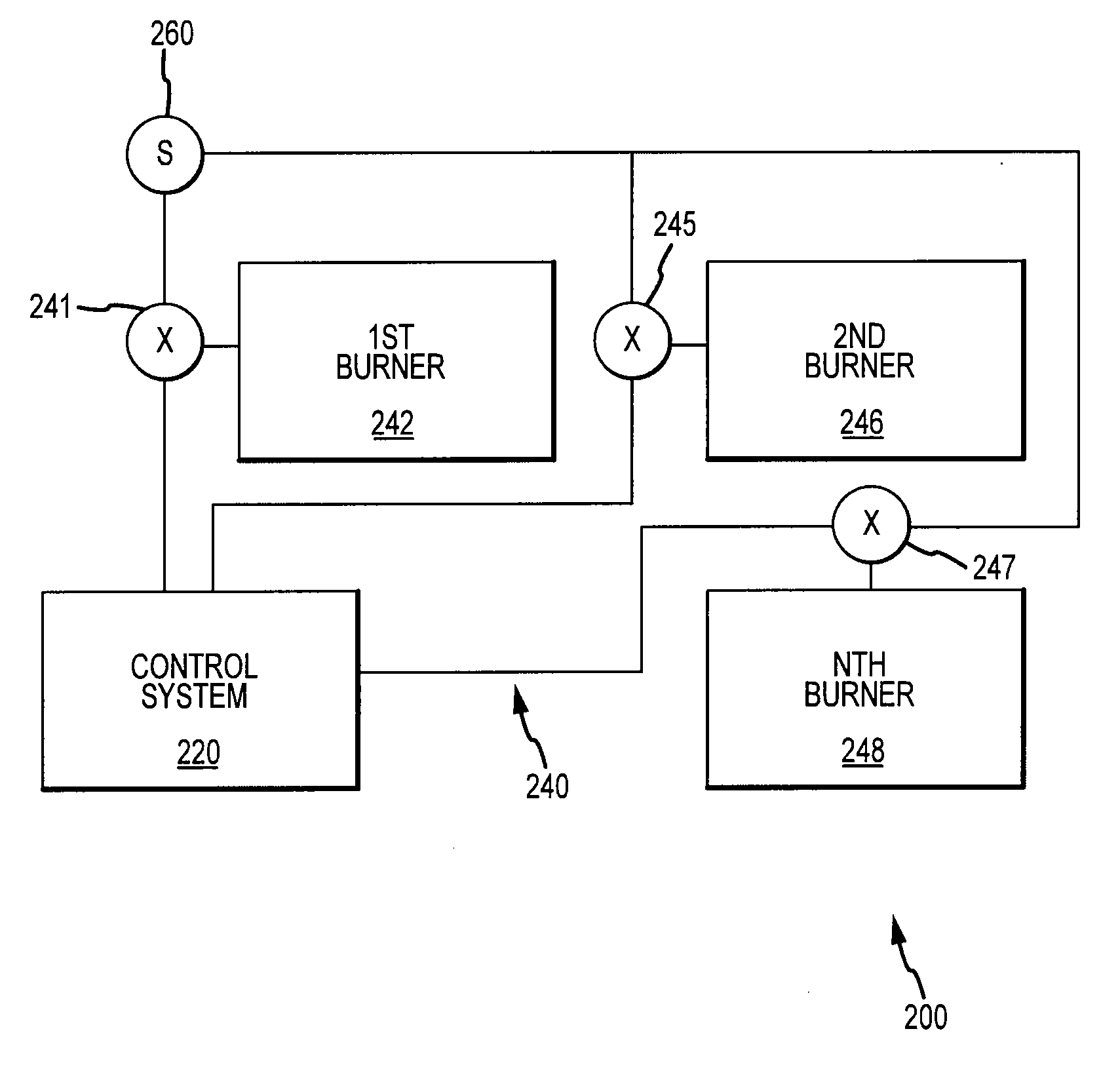
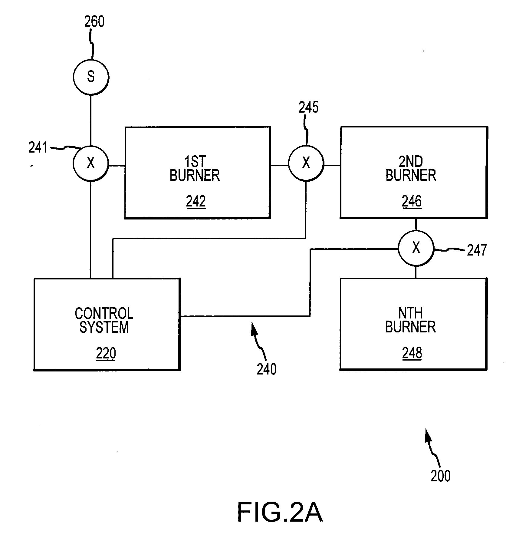
[0026] The description that follows is not intended to limit the scope, applicability, or configuration of the invention in any way; rather, it is intended to provide a convenient illustration for implementing various embodiments of the invention. As will become apparent, various changes may be made in the function and arrangement of the elements described in these embodiments without departing from the scope of the invention. It should be appreciated that the description herein may be adapted to other gas burning applications with multiple independently controlled burning zones and with gas burners having a different size, shape, configuration, material composition, etc. and still fall within the scope of the present invention. Thus, the detailed description herein is presented for the purpose of illustration only and not of limitation.

[0027] The present invention may also be described herein in terms of various functional components. It should be appreciated that such functional ...


PUM


Abstract

A multi-zone gas fireplace system and method for control are provided. An exemplary embodiment of the multi-zone gas fireplace system comprises a firebox, a multi-zone burner system, and a control system. The multi-zone burner system comprises a plurality of burners located in a plurality of zones, a plurality of control valves coupled to the plurality of burners, a gas supply which supplies a gas to the burners, and an ignition source configured to ignite the gas. The control system comprises an input element responsive to a user input, a processor in communication with the input element, and an output element in communication with the processor, such that the control system is operative to automatically provide a variable flame display in conjunction with the multi-zone burner system.

Description

CROSS-REFERENCE TO RELATED APPLICATIONS [0001] This Application claims priority to and the benefit of U.S. Provisional Patent application Ser. No. 60 / 743,420 filed on Mar. 7, 2006 and entitled “MULTI-ZONE GAS FIREPLACE BURNER AND CONTROL SYSTEM AND METHOD.” This Application also claims priority to and the benefit of U.S. Provisional Patent Application No. 60 / 743,413 filed on Mar. 7, 2006, and entitled “REMOTE CONTROLLED GAS FIREPLACE SYSTEM.” Both applications are herein incorporated in their entirety by reference.FIELD OF INVENTION [0002] The present invention relates to a gas fireplace. More particularly, the present invention relates to a multi-zone gas fireplace system and method for control. BACKGROUND OF THE INVENTION [0003] Gas fireplace systems have long been used by individuals to enjoy the benefits of a fireplace experience, but without the disadvantages associated with operating a wood-burning fireplace. For instance, lighting a wood-burning fireplace is generally more di...

Claims


Application Information

Patent Timeline
IPC IPC(8): F23Q2/32A21C13/00F24B1/18
CPCF23N1/002F23N5/00F23N2037/02F24C3/122F24B1/1808F24C3/006F23N2037/10F23N2237/10F23N2237/02
Inventor HILLS, DOUGLAS ERNESTYUEN, TAK MING PETER
Owner FPI FIREPLACE PRODS INT
Why Eureka
Try Eureka