Air flow diversion device for dissipating heat from electronic components

a technology of air flow and diversion device, which is applied in the direction of domestic stoves or ranges, semiconductor/solid-state device details, instruments, etc., can solve the problems of too weak to achieve high-efficiency cooling of electronic components and short serviceable life of electronic components, and achieve efficient reduction of the working temperature of specific electronic components, dissipating heat from electronic components, and high velocity

Inactive Publication Date: 2007-10-11
SUPER MICRO COMP
View PDF8 Cites 21 Cited by
  • Summary
  • Abstract
  • Description
  • Claims
  • Application Information

AI Technical Summary

Benefits of technology

[0007] Accordingly, the primary objective of the present invention is to provide an air flow diversion device for dissipating heat from electronic components, which uses a flow diversion member disposed on a circuit board and selected electronic components are installed in an area close to the flow diversion member. A rapid airflow is caused to follow a specific direction, and is then diverted through airway holes defined in the flow diversion member, and these diverted airflows are further controlled to enable frontal blowing of the specific electronic components disposed close to the flow diversion device, thereby enabling a relatively large amount of airflow having relatively high velocity to blow against circumferential surfaces of the specific electronic components, thus achieving an efficient reduction in the working temperature of the specific electronic components.

Problems solved by technology

However, even though fans are installed in the vicinity of the circuit board to reduce the working temperature of the electronic components, direction the airflow blows is wide-ranging regardless of whether the fans are inducing a draught or ejecting air, and is probably too weak to achieve high-efficient cooling of the electronic components.
Hence, heat dissipation of the electronic components is ineffective, resulting in a short serviceable life of the electronic components.

Method used


Image

  • Air flow diversion device for dissipating heat from electronic components
  • Air flow diversion device for dissipating heat from electronic components
  • Air flow diversion device for dissipating heat from electronic components

Examples


Embodiment Construction

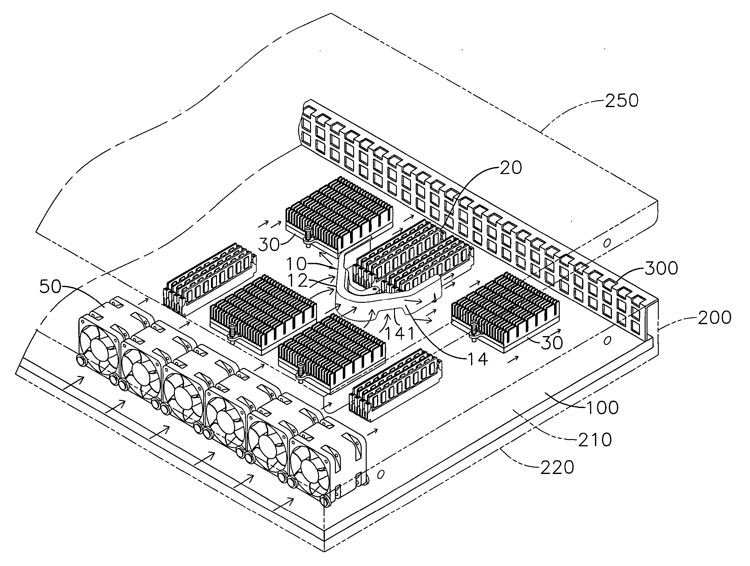
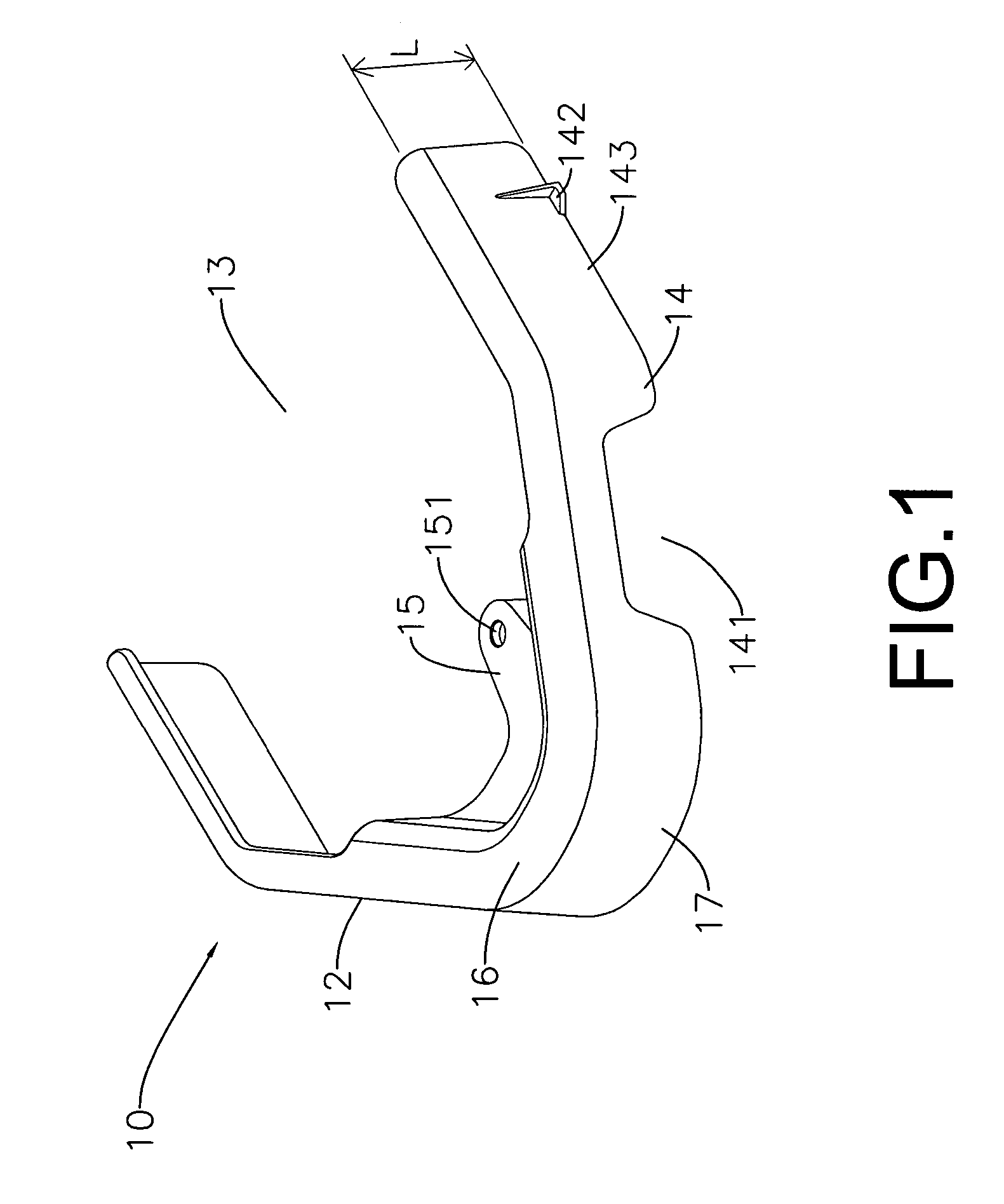
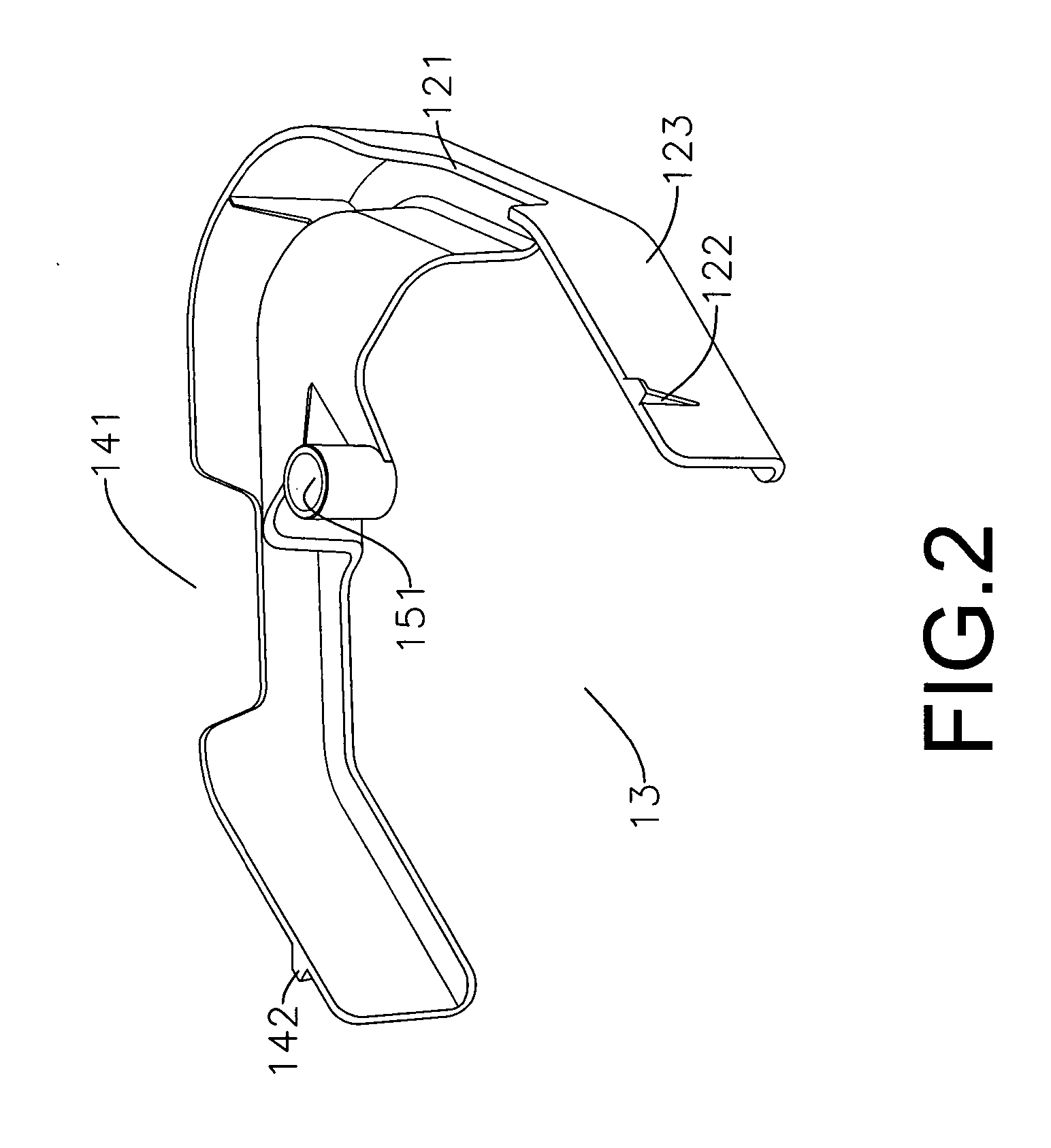
[0014] Referring to FIGS. 1 and 2, which show an air flow diversion device for dissipating heat from electronic components of the present invention, comprising:

[0015] an air flow diversion member 10 of predetermined height L, wherein two or more left and right airway holes 121, 141 are defined in the left and right side walls 12, 14 of the flow diversion member respectively, a rear portion of the flow diversion member 10 is an open space 13, and a connecting portion 15 having a connecting hole 151 is configured on the body of the flow diversion member 10; wherein the connecting portion 15 can be fixedly bolted to a circuit board 100.

[0016] An airflow following a specific direction passes through the left and right airway holes 121,141 and diverted into the open space 13.

[0017] Referring to FIG. 4, wherein a first set of electronic components 20 are soldered to a surface of the circuit board 100 positioned in the open space 13. The left and right airway holes 12l, 141 divert and b...


PUM


Abstract

An air flow diversion device for dissipating heat from electronic components, including: an air flow diversion member of predetermined height, wherein two or more left and right airway holes are defined in left and right side walls of the flow diversion member respectively, and a rear side of the flow diversion member is an open space, a connecting portion having a connecting hole is configured on the air flow diversion member, and the connecting portion can be fixedly bolted to a circuit board. An airflow is caused to follow a specific direction and diverted through the left and right airway holes into the open space, thereby enabling a relatively large amount of airflow having relatively high velocity to blow against circumferential surfaces of specific electronic components, thus achieving an efficient reduction in the working temperature of the specific electronic components.

Description

BACKGROUND OF THE INVENTION [0001] (a) Field of the Invention [0002] The present invention relates to an air flow diversion device for dissipating heat from electronic components, and more particularly to an air flow diversion device for use on circuit boards within an industrial host computer case, which uses a flow diversion member having airway holes and flow diversion side walls to cause the direction of airflow to align with and blow against specific electronic components on a circuit board, thereby achieving efficient heat dissipation and cooling of the specific electronic components. [0003] (b) Description of the Prior Art [0004] All circuit boards within conventional industrial host computer cases have various types of chips, computer memory and central processing units soldered thereon, and these electronic components are increasing along with the variety of functionality, for example, when a host computer needs to have utility to control many tool devices, distant monitori...

Claims


Application Information

Patent Timeline
Patent Type & Authority Applications(United States)
IPC IPC(8): H05K7/20
CPCG06F1/20H01L23/467H05K7/20727H01L2924/0002H01L2924/00
Inventor CHEN, RICHARDLEE, ALAN
Owner SUPER MICRO COMP
Why Eureka
Try Eureka