Electronic aerosol device

a technology of aerosol and electronic components, which is applied in the direction of atomized substances, machines/engines, applications, etc., can solve the problems of hand fatigue, add to the complexity and cost of the device, and limit the usefulness of the spray devi

Inactive Publication Date: 2007-10-11
HELF THOMAS A +2
View PDF99 Cites 87 Cited by
  • Summary
  • Abstract
  • Description
  • Claims
  • Application Information

AI Technical Summary

Benefits of technology

[0008] According to one embodiment of the present invention, a device for dispensing a fluid comprises a housing having an internal power source and a mounting assembly adapted for receiving a replaceable fluid reservoir. The fluid reservoir includes a capillary element for movement of the fluid to a discharge end thereof. A mechanism is disposed within the housing and is energized by the internal power source for vibrating a perforated discharge plate disposed adjacent the discharge end of the capillary element. The mechanism provides sufficient vibratory movement in a dispensing state to pump the fluid from the discharge end through the discharge plate and into the atmosphere. A control is carried by the housing and is disposed beneath the mounting assembly. The control provides an interface for a user to select at least one of a timed mode of operation, an automatic mode of operation dependent upon a sensor output developed by a sensor, and a manual mode of operation. The mounting assembly is further adapted to receive the replaceable fluid reservoir in a manner that allows same to be visually inspected during an in-use condition.

Problems solved by technology

Such spray devices are of limited usefulness because single action continuous spraying of a fluid cannot be accomplished.
While such devices are more useful in those occasions when a substantial quantity of product is to be released, some consumers find the force necessary to hold the valve assembly in an open condition to result in hand fatigue.
Also, the need for propellants and / or devices (such as a piston to contain the propellant in an application where the propellant is to remain isolated from the atmosphere) undesirably adds to the complexity and cost of the device.

Method used


Image

  • Electronic aerosol device
  • Electronic aerosol device
  • Electronic aerosol device

Examples


Embodiment Construction

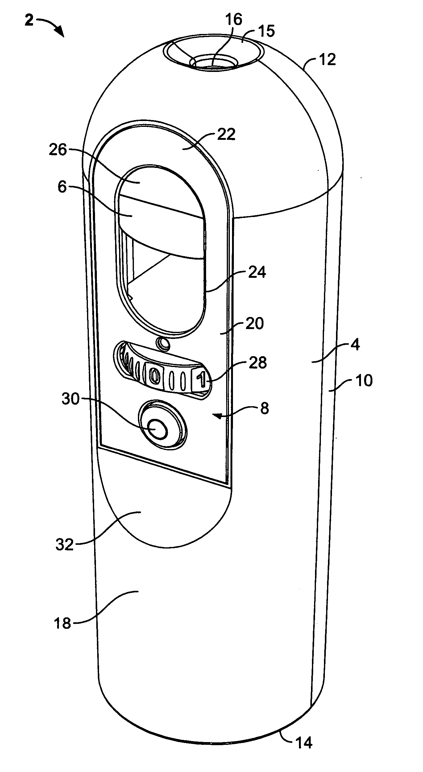
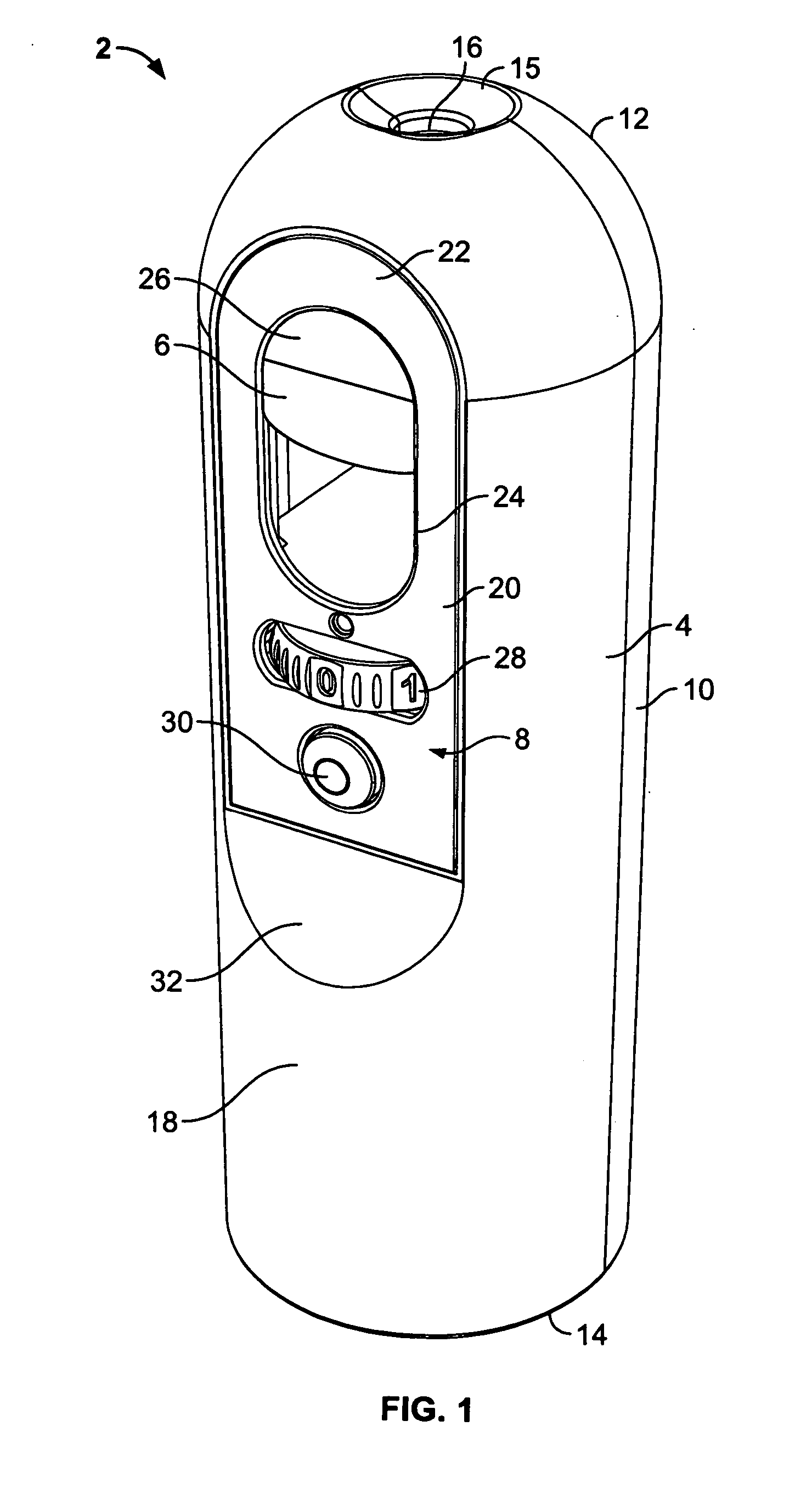
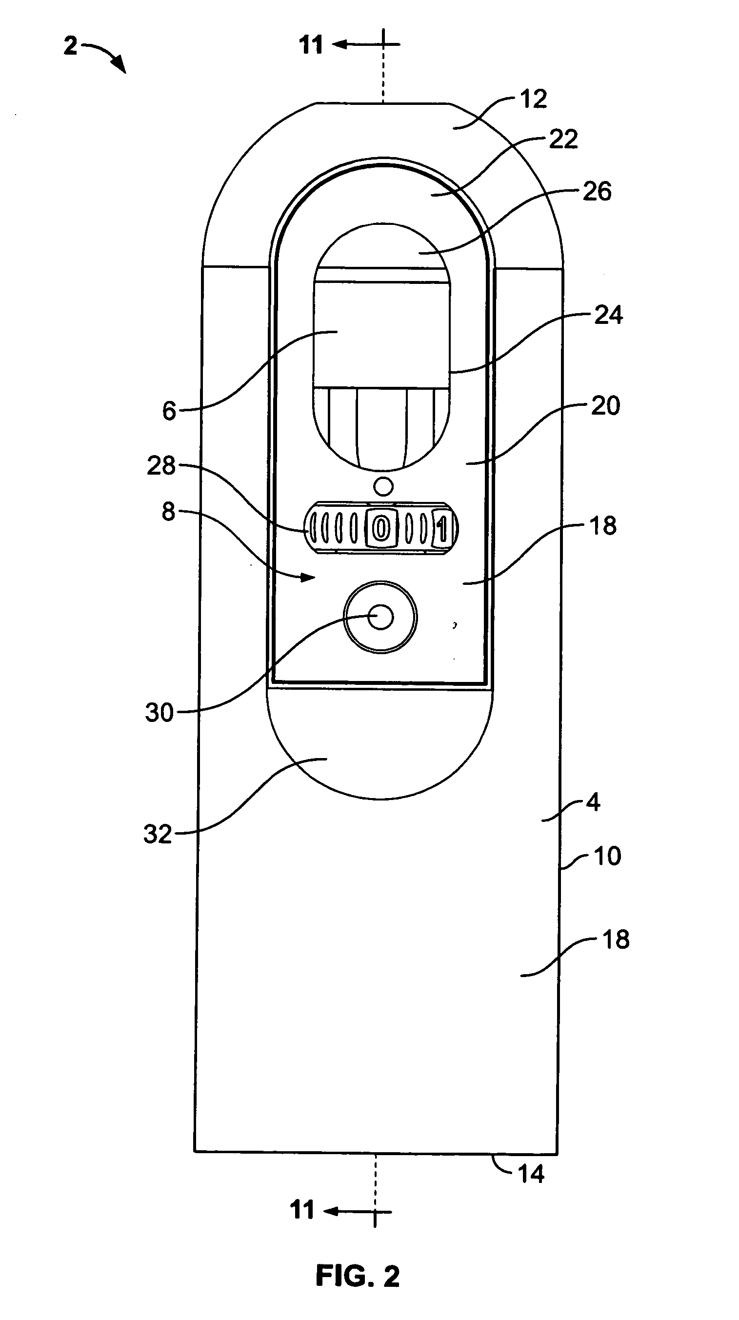
[0041]FIGS. 1-5 generally depict one embodiment of a fluid emitting device 2. The device 2 generally comprises a telescoping housing 4, a fluid reservoir 6, and a control panel 8. The device 2 is typically operated in at least one of two in-use conditions or modes of operation. In a first operational mode the user holds the device 2 in his or her hand by gripping the housing 4, whereupon fluid is emitted from the reservoir 6 by manipulation of the control panel 8. In a second operational mode the housing 4 of the device 2 is disposed on a support surface and fluid is emitted upon receipt of an activation signal from a timer and / or a sensor 9. The emitted fluid may be a fragrance, sanitizing agent, household cleaner, insecticide, insect repellant, deodorizing liquid, or, for that matter, any fluid (liquid and / or gas), whether disposed in a carrier fluid or not.

[0042] The telescoping housing 4 is typically made from a molded plastic, such as polypropylene. The housing 4 comprises a c...


PUM

PropertyMeasurementUnit
dwell timeaaaaaaaaaa
diameteraaaaaaaaaa
diameteraaaaaaaaaa

Abstract

A device for dispensing a fluid comprises a housing having an internal power source and a mounting assembly adapted for receiving a replaceable fluid reservoir. The fluid reservoir includes a capillary element for movement of the fluid to a discharge end thereof. A mechanism is disposed within the housing and is energized by the internal power source for vibrating a perforated discharge plate disposed adjacent the discharge end of the capillary element. The mechanism provides sufficient vibratory movement in a dispensing state to pump the fluid from the discharge end through the discharge plate and into the atmosphere. A control is carried by the housing and is disposed beneath the mounting assembly. The control provides an interface for a user to select at least one of a timed mode of operation, an automatic mode of operation dependent upon a sensor output developed by a sensor, and a manual mode of operation. The mounting assembly is further adapted to receive the replaceable fluid reservoir in a manner that allows same to be visually inspected during an in-use condition.

Description

CROSS REFERENCE TO RELATED APPLICATIONS [0001] Not Applicable REFERENCE REGARDING FEDERALLY SPONSORED RESEARCH OR DEVELOPMENT [0002] Not Applicable SEQUENTIAL LISTING [0003] Not Applicable BACKGROUND OF THE INVENTION [0004] 1. Field of the Invention [0005] The present disclosure relates to discharging a fluid from a spray device, and more particularly, to a method and apparatus for discharging a fluid through a nozzle using a piezoelectric pump assembly. [0006] 2. Description of the Background of the Invention [0007] Manually-operated hand-held spray devices comprise pump-type sprayers that require repeated manual activation of a pump assembly to emit a fluid. Such spray devices are of limited usefulness because single action continuous spraying of a fluid cannot be accomplished. Instead, a user must repeatedly pump the assembly in order to emit a substantial quantity of product. In other hand-held spray devices, such as aerosol containers, single action continuous spraying is achie...

Claims


Application Information

Patent Timeline
Patent Type & Authority Applications(United States)
IPC IPC(8): B05B3/04B05B1/08
CPCA01M1/205A61L9/14B05B12/002B05B17/0646B05B12/12B05B17/0607B05B12/02
Inventor HELF, THOMAS A.FURNER, PAUL E.PAAS, EDWARD L.
Owner HELF THOMAS A
Why Eureka
Try Eureka