Power-on reset circuit using flip-flop and semiconductor device having such power-on reset circuit
- Summary
- Abstract
- Description
- Claims
- Application Information
AI Technical Summary
Benefits of technology
Problems solved by technology
Method used
Image
Examples
first embodiment
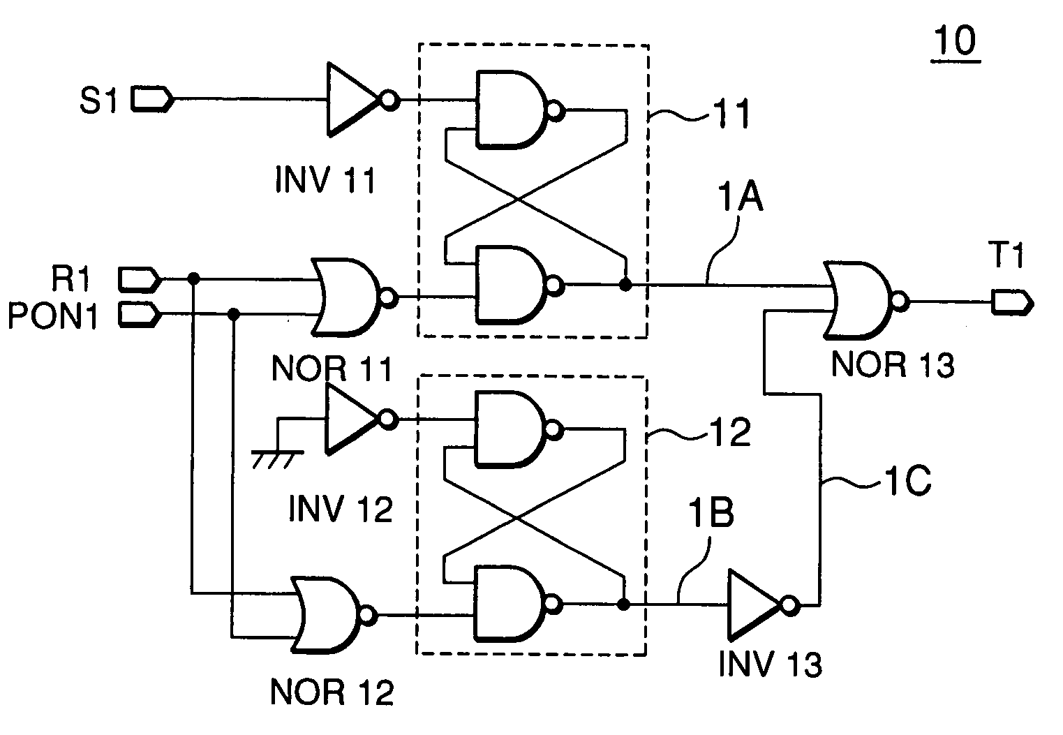
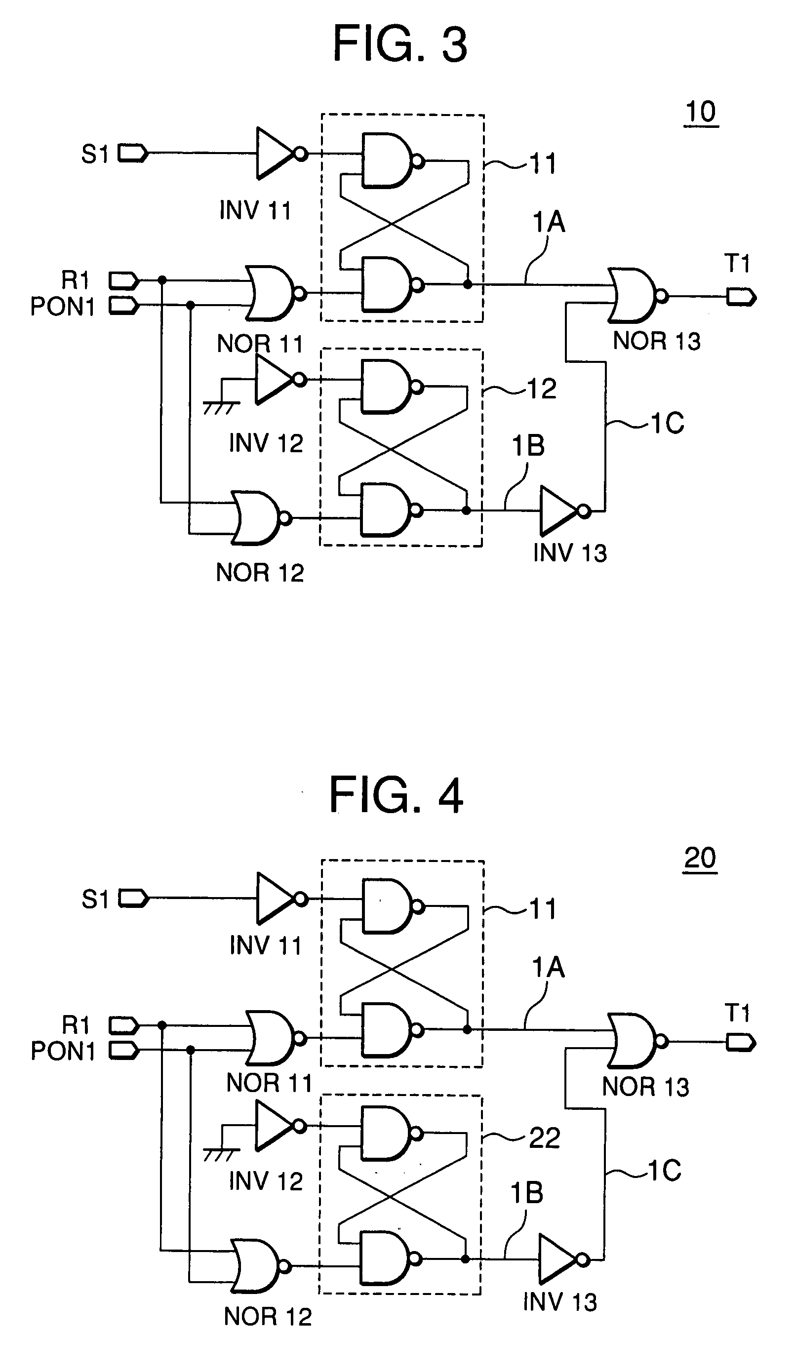
[0035]A first embodiment of the present invention will be described with reference to FIGS. 3 and 4. FIGS. 3 and 4 show a power-on reset circuit using a flip-flop. A power-on reset circuit 10 shown in FIG. 3 is composed of flip-flops 11 and 12, inverter circuits INV11, INV12 and INV13, and NOR circuits NOR11, NOR12 and NOR13. A power-on reset circuit 20 shown in FIG. 4 has same configuration as that of the power-on reset circuit 10 except that the flip-flop 12 of the power-on reset circuit 10 of FIG. 3 is replaced with a flip-flop 22.
[0036]The flip-flop 11 in the power-on reset circuit 10 receives, as set input, a set signal S1 after being inverted by the inverter circuit INV11. The flip-flop 11 receives, as reset input, an output signal from the NOR circuit NOR11 receiving a reset signal R1 and a power-on reset signal PON1 as input. The flip-flop 12 receives, as set input, output from the inverter circuit INV12 receiving an input signal having ground potential. The flip-flop 12 rec...
second embodiment
[0051]A second embodiment of the present invention will be described with reference to FIGS. 5 and 6. In this embodiment, the dummy flip-flop according to the first embodiment is multiplexed, and two dummy flip-flops are provided. FIG. 5 shows a first multiplexed power-on reset circuit 30, while FIG. 6 shows a modification thereof, a second multiplexed power-on reset circuit 30-1. The power-on reset circuit 30 shown in FIG. 5 is composed of a setting flip-flop 31, dummy flip-flops 32 and 33, inverter circuits INV31, INV32, INV33, INV34, and INV35, NOR circuits NOR31, NOR32, NOR33, and NOR34. The power-on reset circuit 30-1 shown in FIG. 6 has dummy flip-flops 34 and 35 in place of the dummy flip-flops 32 and 33 of FIG. 5, while the other configuration is the same as the power-on reset circuit 30.
[0052]The setting flip-flop 31 of the power-on reset circuit 30 receives, as set input, a set signal S3 after being inverted by the inverter circuit INV31. The setting flip-flop 31 receives,...
third embodiment
[0064]A third embodiment of the present invention will be described with reference to FIGS. 7 and 8. According to this embodiment, a flip-flop of a power-on reset circuit generating another latch signal is utilized as a dummy flip-flop. FIG. 7 shows a power-on reset circuit 50, while FIG. 8 shows a modification thereof, a power-on reset circuit 50-1.
[0065]In the first and second embodiments described above, the latch signal is set to an expected value at power-on by adding the dummy flip-flop. It is also described that the effect is enhanced as the number of the dummy flip-flops is increased. However, the increase of the number of the dummy flip-flops obviously leads to the increase of the chip surface area. The third embodiment relates to configuration for avoiding this. According to the third embodiment, latch signals T5A and T5B are output from flip-flops 51 and 52 and latch separate commands, respectively. These latch signals T5A and T5B are selected such that they are not activ...
PUM
 Abstract
Description
Claims
Application Information
 - R&D
- Intellectual Property
- Life Sciences
- Materials
- Tech Scout
- Unparalleled Data Quality
- Higher Quality Content
- 60% Fewer Hallucinations
Browse by: Latest US Patents, China's latest patents, Technical Efficacy Thesaurus, Application Domain, Technology Topic, Popular Technical Reports.
© 2025 PatSnap. All rights reserved.Legal|Privacy policy|Modern Slavery Act Transparency Statement|Sitemap|About US| Contact US: help@patsnap.com


